Corbin Russwin A5 and N5 Lever Trim for ED8000 Series Wide Stile Installation Instructions_FM125
Open the original PDF document
View PDFInstallation Instructions
ED8000 Series Pushbar Exit Device A5 and N5 Lever Trim

Important
- For wood and metal doors.
- Failure to follow these instructions could affect operation of this product and void warranty.
- Exit devices must be securely fastened to properly reinforced doors with fasteners which will not loosen or pull out. Add reinforcement when necessary.
- Before installing be sure exit device is proper hand for door.
How to Determine Hand of Door
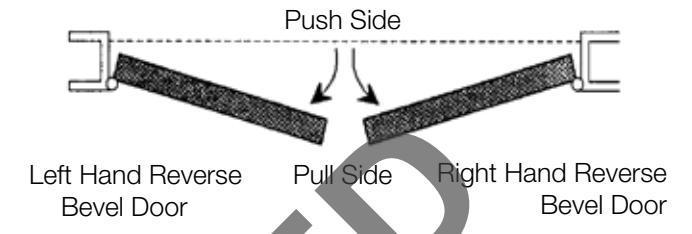
1
Mark Centerline
Establish centerline of device by drawing line across door and stop, 40-5/16" (1.02m) above finished floor unless doors have been pre-prepped. (Figure 1) 40-5/16" (1.02m) Finished Floor Line
2
Spot and Drill Template Holes
CAUTION: When installed with removable mullion, see instruction sheet packed with mullion.
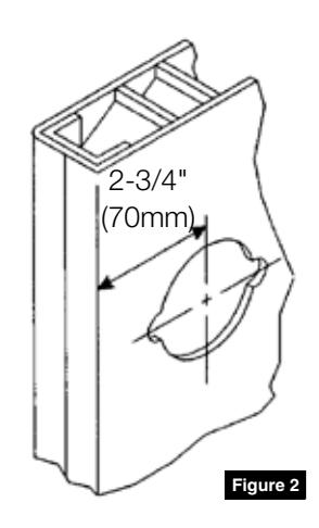
If door is not prepped with 2-3/4" (70mm) backset cylindrical lock cut-out, use template furnished. Spot and drill mounting holes for device, latch assembly and trim (if furnished).
If door has ANSI A115.2 cylindrical lock cut-out:
- Extend horizontal and vertical lines of cut-out. (Figure 2)
- 2. If frame has 5/8" (16mm) stop, align centerlines on template with centerlines on door. Spot, drill and tap mounting holes for device, latch assembly, trim (if furnished), and strike (if applicable).
- 3. If frame has 1/2" (13mm) stop, align centerlines on template with centerlines on door and spot mounting holes for device and trim (if furnished). Then move template up against stop to mark strike holes (if applicable). Note special shim which must be mounted behind strike. Drill and tap all required holes.
ED8000 Series Pushbar Exit Device
A5 and N5 Lever Trim
Installation Instructions

3 Cut Pushbar (If Required)
Follow instructions packed with device.
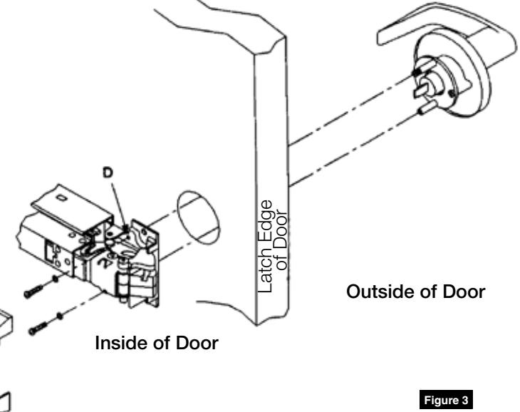
4 Install Trim
- 1. Insert trim assembly into 2-1/8" hole and place device against inside surface of door. Be sure cross hole in device head engages onto tailpiece of trim assembly.
- 2. Insert two (2) fillister head screws (packed with trim) into holes D of device head and thread into trim posts. Continue with instructions packed with bar.
ED8000 Series Pushbar Exit Device
A5 and N5 Lever Trim
Installation Instructions

Removal and Re-installation of Standard Cylinder
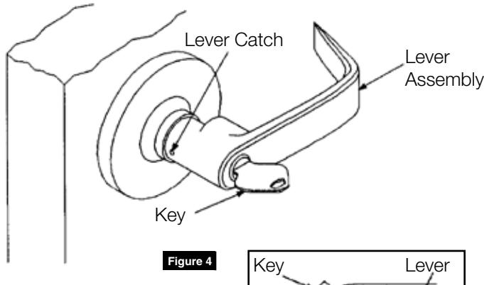
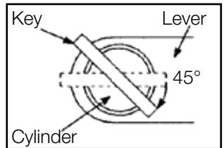
Remove Lever
- 1. Insert key and turn 45° clockwise.
- 2. Insert removing tool into hole on side of lever and depress retainer.
- 3. While holding retainer in depressed position, pull lever off.
Remove Cylinder
- 1. Remove key.
- 2. Remove plastic filler.
- 3. Slide cylinder out.
Reinstall Cylinder
- 1. Slide cylinder into lever.
- 2. Install plastic filler.
Reinstall Lever
- 1. Insert key part way. Slide lever onto spindle as far as it will go, using key to guide cylinder into engagement.
- 2. Insert key fully and turn. Holding key turned, push lever the rest of the way onto spindle.
- 3. Remove key and pull lever to be sure it is properly retained on spindle.
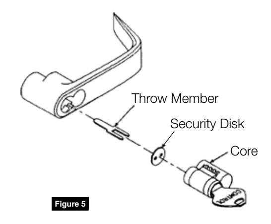
Interchangeable Core Locksets
If figure-8 core is already installed in lever, no further action is necessary. Otherwise, locate throw member packet and special CONTROL key. Place security disk onto throw member prongs and insert throw member into holes in rear of core. Insert CONTROL key and turn 15° clockwise to retract control lug. Slide core with throw member into lever. As shown here, core must be installed with keyed plug toward edge of door. Turn CONTROL key counter-clockwise and remove.
CONTROL key has no further use in lockset installation and must be safeguarded for return to Security personnel when installation is complete.

Corbin Russwin 225 Episcopal Road Berlin, CT 06037 Phone: 800-543-3658 Fax: 800-447-6714 corbinrusswin.com
Copyright © 2018 Corbin Russwin, Inc., an ASSA ABLOY Group company. All rights reserved. Reproduction in whole or in part without the express written permission of Corbin Russwin, Inc. is prohibited.