Corbin Russwin 808 Mullion for ED4000 Series Narrow Stile Installation Instructions_FM191
Open the original PDF document
View PDFInstallation Instructions
808 Mullion for ED4000 Series Narrow Stile Exit Devices
4004 4010
In U.S.: In Canada: Corbin Russwin, Inc. ASSA ABL-225 Episcopal Road 160 Four Vi Berlin, CT 06037 USA Vaughan, C
www.corbinrusswin.com
ASSA ABLOY Door Security Solutions Canada 160 Four Valley Drive
Vaughan, Ontario, Canada L4K4T9 www.assaabloy.ca
Technical Product Support: Phone: 888-607-5703
FM191 (10/15)
808 Mullion for ED4000 Series Narrow Stile Exit Devices

Installation
A. Installation Sequence
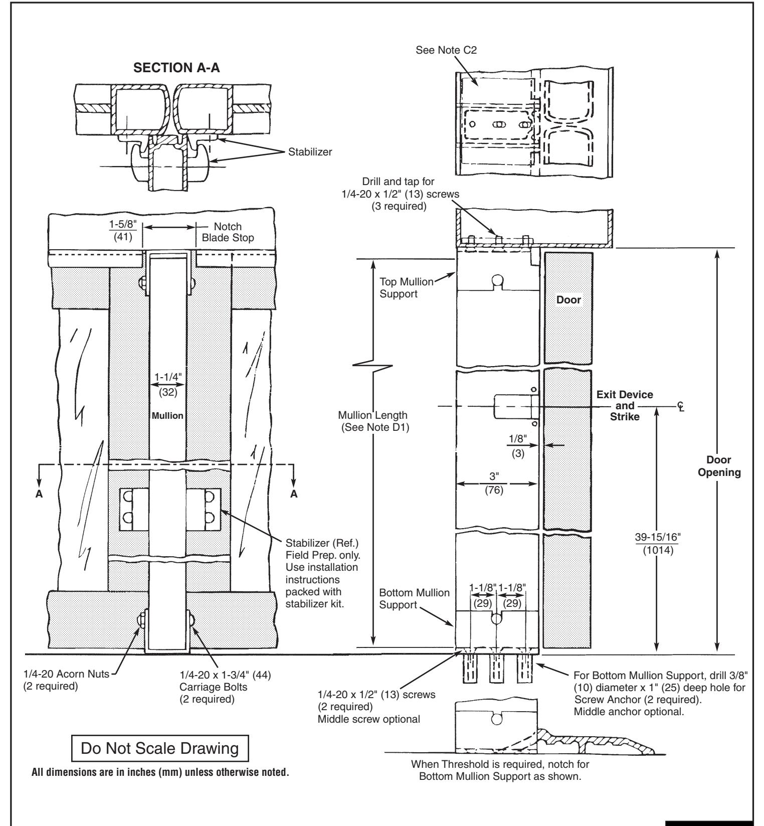
1. Close both doors. Find the centerline between both doors and mark line perpendicular to door face on frame soffit or header. Drop plumb line to floor and mark line on floor perpendicular to doors. This is the centerline of the mullion.
B. Bottom Support - Floor Mounted
- 1. Using Bottom Mullion Support as template, center support on marked line 1/8" (3mm) from closed door.
- 2. Spot and prepare (2) outside screw anchor holes, middle anchor optional.
- 3. Install screw anchors: Place the anchor in the prepared hole, place punch through the threaded hole of the anchor, drive with a hammer until seated, remove punch and bolt mullion support to floor with (2)1/4 20 x 1/2" (13mm) screws.
C. Top Support - Frame Mounted
- 1. Using Top Mullion Support as a template, center with mark on frame soffit and flush with door side of stop.
- 2. Spot and prepare (3) holes (#7 drill .201" (5mm) diameter hole and tap 1/4-20 thread.) Note: All mounting holes in soffit should be provided with reinforcement plates by the manufacturer.
- 3. Install Top Mullion Support to frame soffit with (3)1/4-20 x 1/2" (13mm) screws.
D. Prepare and Install Mullion
- To determine Mullion length, measure distance from finished floor to top mounting surface upon which Top Mullion Support is mounted. Subtract 1/2" (13mm). Cut to this dimension on TOP END of mullion. Note: Mullion is furnished to suit 8 foot (2438mm) high doors. If field cut is required, mark and drill .281 (7mm) diameter hole thru both walls on TOP END of mullion.
- 2. Install Mullion into supports. Install and tighten top and bottom 1/4-20 nuts and bolts.
E. Mullion Stabilizer Installation
1. See Mullion Stabilizer Kit instructions for location and installation.