Command Access PD29 Delayed Egress Instructions
Open the original PDF document
View PDF


Armed: When armed, this device activates an internal blocking mechanism to prevent exiting the door from the inside until the proper release sequence has been completed.
Release Delay: When an attempt is made to open the door from the inside, the device sounds an alarm and initiates a countdown.
Free Exit: Upon completion of the Release Delay countdown, the device will release the push bar and allow free exit from the door until it is reset. An alarm will continue to sound until the device is reset.
Fire Contacts: The power supply for this device must be connected to a fire alarm to cut power to the device, allowing immediate egress in the event of an emergency.
*IMPORTANT*
Local regulations and building codes may dictate specific requirements for the installation and usage of these devices.
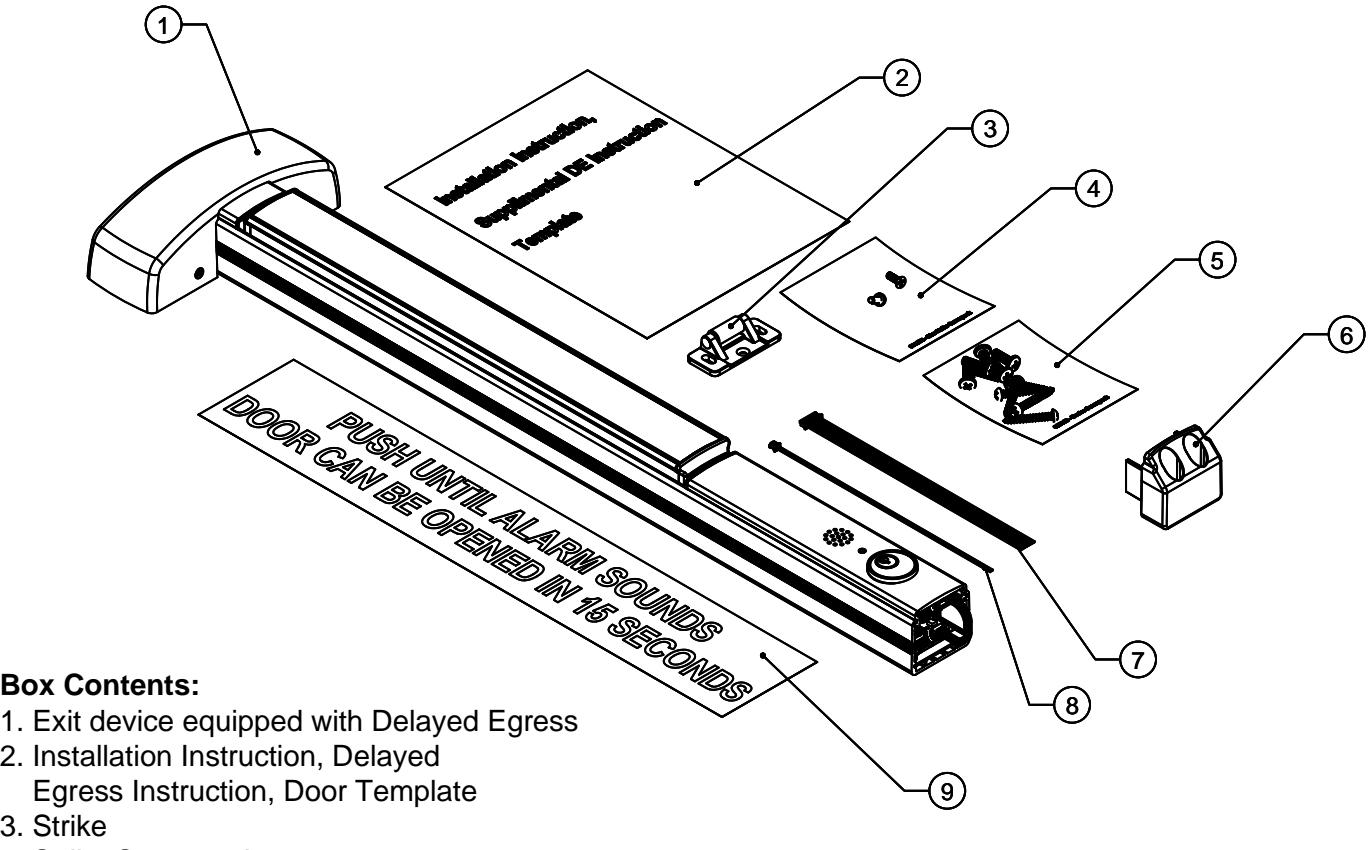
- 3. Strike
- 4. Strike Screwpack
- 5. Device Screwpack
- 6. End Cap
- 7. 8 pin wiring harness with leads
- 8. 2 pin wiring harness with leads
- 9. Warning signage for door


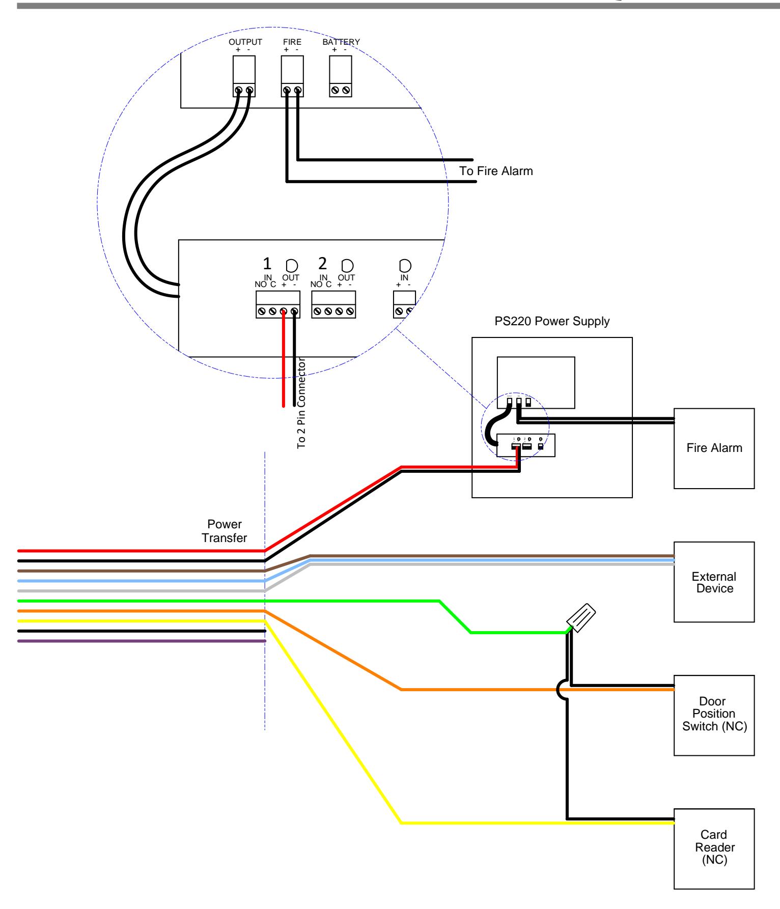
Fire Alarm – Power Supply
Usage: Required by Code
Power supply must be wired to cut power to the DE device on activation of fire alarm. The example wiring diagram in this manual shows how device should be wired if using our PS220 power supply. A UL 294 rated power supply providing a minimum of 1 Amp at 24VDC (+/-10%) with fire alarm link is required.
Inhibit Contact
Usage: Optional Type: Normally Open
Contact closure allows free egress/ingress without sounding the alarm. After Inhibit completes, the system resets automatically when contact position conditions are satisfied (door position switch and optional latch monitor switch). Inhibit is usually wired to an access control system to allow entry from the outside or exit from the inside without alarming the device. When not used for Inhibit, this input can be used to reset a device in alarm.
Door Position Switch (DPS)
Usage: Preferred Type: Normally Closed
The Door Position Switch input senses door opening. If the door has been opened without using the Inhibit feature, the internal alarm will sound. The DPS contact must be closed to arm the device including after inhibit has been used. If not used, bypass DPS by closing circuit.
Relay Contacts
Usage: Optional Type: SPDT
Opens or closes contact upon system arming. Can be used to signal security system when device is armed. Relay contacts will change state when device alarms and during Inhibit.
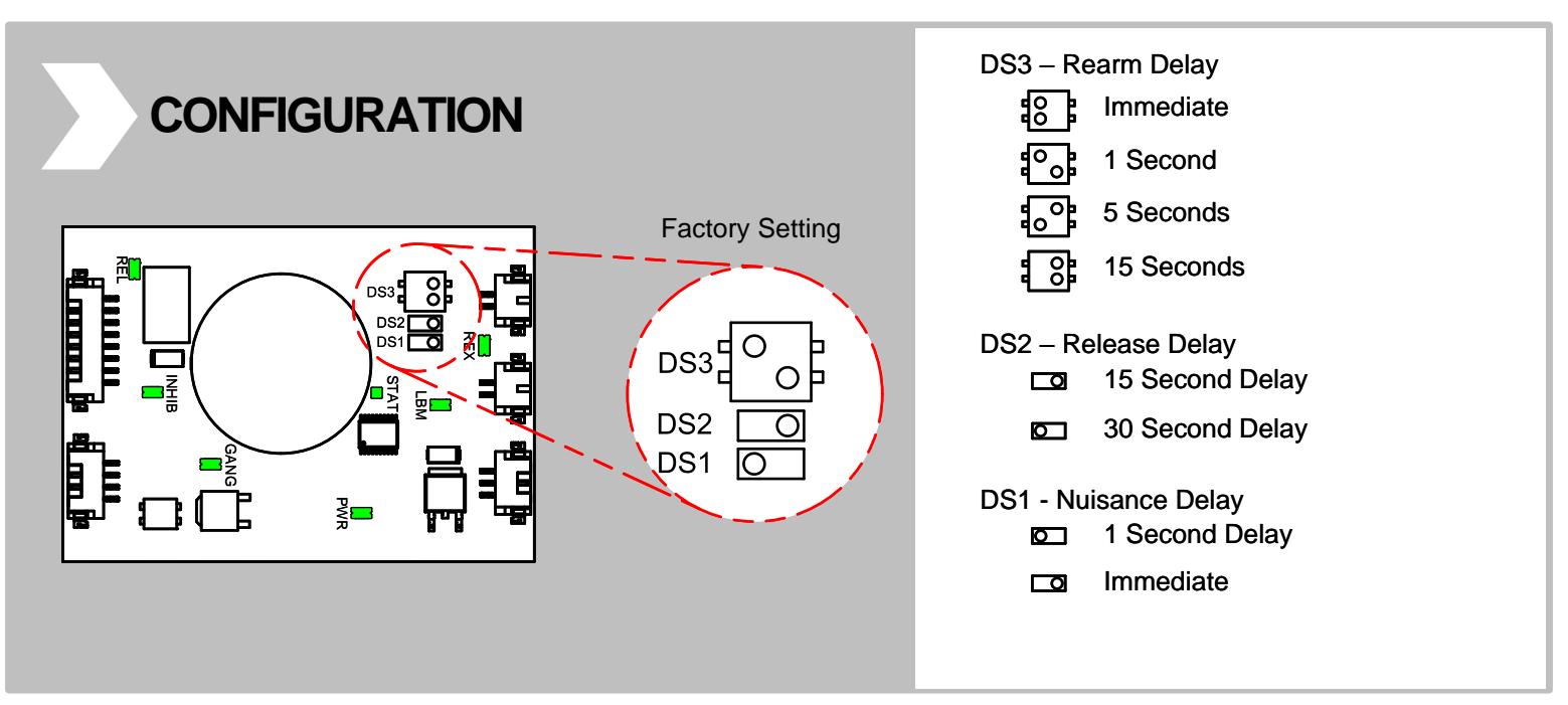
Nuisance Delay
Configurable: Immediate, 1 second
The Nuisance Delay starts from the first moment the push bar is pressed. If set to Immediate, the device will immediately begin the Release Delay. If set to 1 second, the device will sound a beep when pressed. If the device is released before 1 second it will return to the previous, armed state. If held for longer than 1 second the device will proceed to the Release Delay. This is useful in public areas where the device may be accidentally activated.
Release Delay
Configurable: 15 seconds, 30 seconds
When the Release Delay is initiated, the push bar will remain locked and a warning beep will sound for the configured number of seconds (less any time already occupied by the Nuisance Delay). Once started, the Release Delay sequence cannot be stopped and the device will allow egress after the configured time has passed.
Rearm Delay
Configurable: Immediate, 1 second, 5 seconds, 15 seconds
The time the device waits to arm following arming with the Key Switch or Inhibit Input. The device will arm when door closes (and DPS is satisfied) and the rearm delay has completed. Rearm delay can also be set to 15 seconds to allow door to close after Inhibit when DPS is not used.


Key Switch
- The Key Switch Arms or Disarms the device.
- Turning the Key Switch counter-clockwise arms the device (following the Rearm Delay)
- Turning the Key Switch clockwise Disarms the device immediately
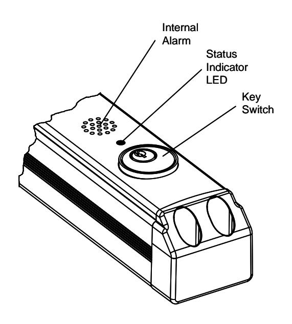
Status Indicator LED
- Armed Solid Red LED
- Disarmed / Alarmed Red LED is off
- Inhibit Active Red LED is off
Internal Alarm
- Nuisance Delay Active Short continuous beep
- Release Delay Initiated Long continuous beep
- Alarming Pulsing Beep


*IMPORTANT*
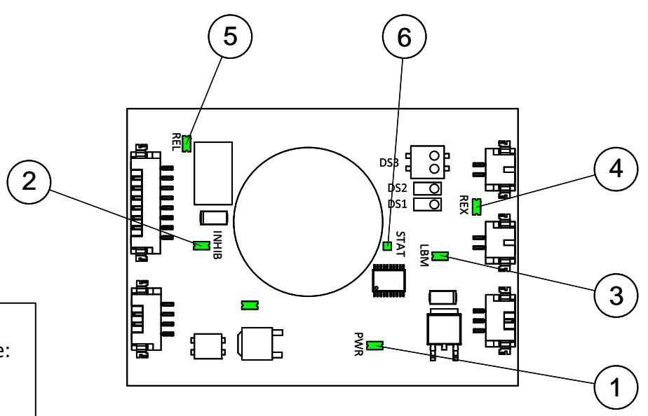
For device to arm, the following must be true: PWR, REX, LBM, STAT must be lit INHIB must not be lit
| Description | Status | Troubleshooting | ||
|---|---|---|---|---|
| 1 | PWR |
On = Power Present
Off = No Power Present |
Check power to key switch board
Ensure key switch is in ON position Ensure fire alarm link is closed at the power supply Check all connections |
|
| 2 | INHIB |
On = Inhibit Engaged
Off = Inhibit not Engaged |
Ensure circuit is a Normally Open and is in the open state
Check all connections |
|
| 3 | LBM/DPS |
On = Loop Closed
Off = Loop Open |
Ensure sure latch is extended
Ensure Door Position Switch is Normally Closed and in closed state Check all connections |
|
| 4 | REX |
On = Loop Closed
Off = Loop Open |
Make sure push pad is not depressed
Check all connections |
|
| 5 | RELAY |
On = Armed State
Off = Not Armed |
Check all connections | |
| 6 | STAT |
On = Armed
Off = Not Armed |
Power needs to be present, and all inputs need to be in their normal state
(INHIB/REX/DPS/LBM) Check all connections |
|


ELECTRICAL SPECIFICATIONS
Power Supply Requirements:
- UL 294 rated
- 1 Amp at 24VDC +/-10%
- Fire alarm link to cut power to DE device when active
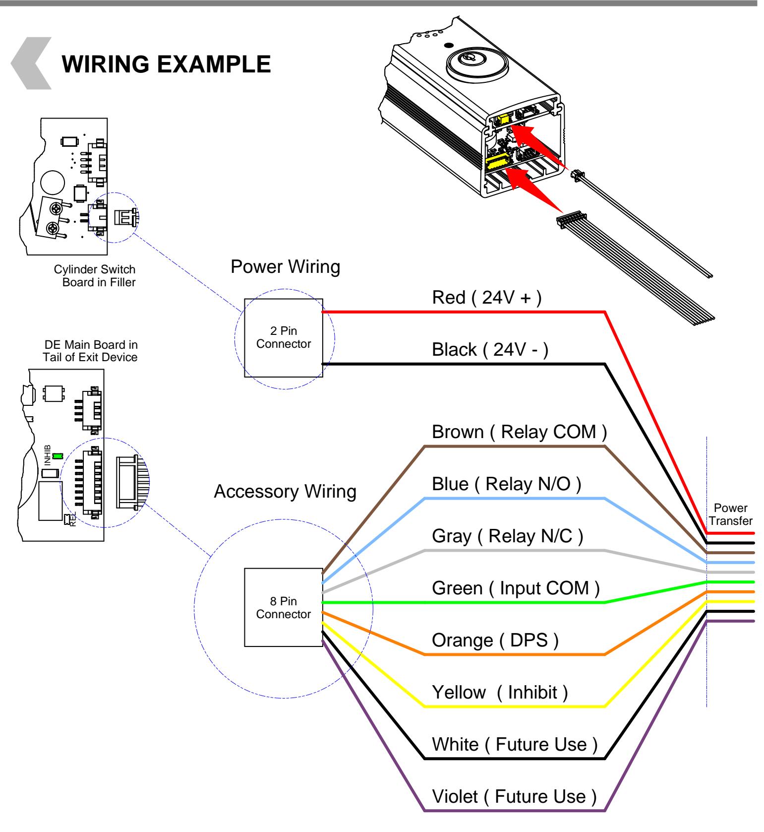
| Description | Color | Function | Specification | Wire Type and Distance |
|---|---|---|---|---|
| 2 Pin Harness | Red | 24VDC + | 1 AMP Inrush, 250 mA holding | 18 gauge up to 300' |
| Black | 24VDC - | |||
| Brown | Relay Common | Security Relay Output Common |
22 gauge up to 98.5' for signal contacts
18 gauge up to 98.5' for power contacts Relay rated 1Amp @ 24VDC |
|
| Blue | Relay NO | Security Relay Output Normally Open | ||
| Gray | Relay NC | Security Relay Output Normally Closed | ||
| 8 Pin Harness | Green | Input Common | Input Common Ground | 22 gauge up to 500' |
| Orange | Door Position Switch | Input DPS Normally Closed | ||
| Yellow | Inhibit | Input Inhibit Normally Open | ||
| White / Violet | Future Use |

CERTIFICATIONS
- Listed for UL305 "Panic"
- Listed for UL10C "Fire Exit Hardware" (for devices ordered with fire rating only)
- Listed for UL294 "Controlled Egress Equipment and Systems or Delayed Egress Equipment and Systems", Access Control Endurance Level I
- Certified to ANSI/BHMA A156.3 Grade 1
- Meets International Building Code (IBC) for Delayed Egress and Controlled Egress Systems.
- Meets requirements of the BAA as a COTS product manufactured in the United States