Command Access PD29 CVR Installation Instructions
Open the original PDF document
View PDFPD27/28/29/30 INSTALLATION INSTRUCTIONS CVR DEVICE

1. PREPARE DOOR
- Prepare door according to template.
- Refer to trim template if installing trim.
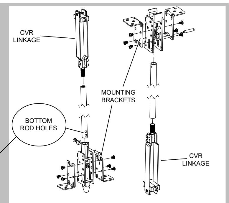
2. ASSEMBLE RODS & LATCHES
Thread CVR linkage into each rod to approximate middle of threads
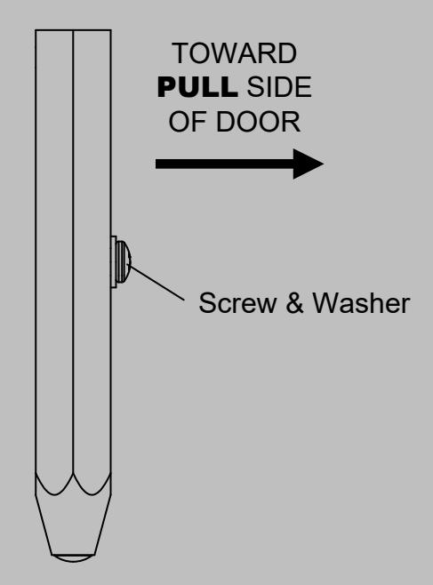
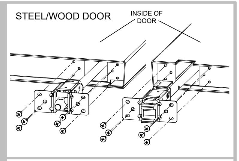
Steel Door – Attach mounting brackets as shown Wood Door– Attach single mounting bracket on each latch (toward hinge side)
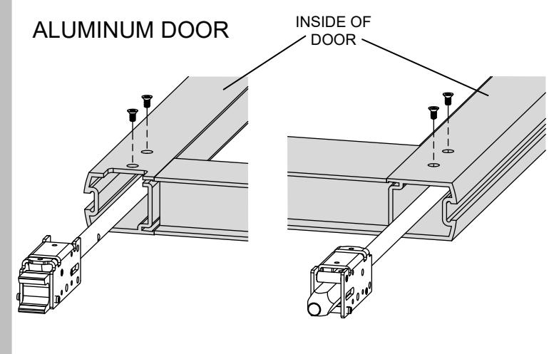
Alum Door – Continue to next step
THRESHOLD NOTE:
When using ½" threshold, move bottom rod attachment pin to upper hole in bottom rod.
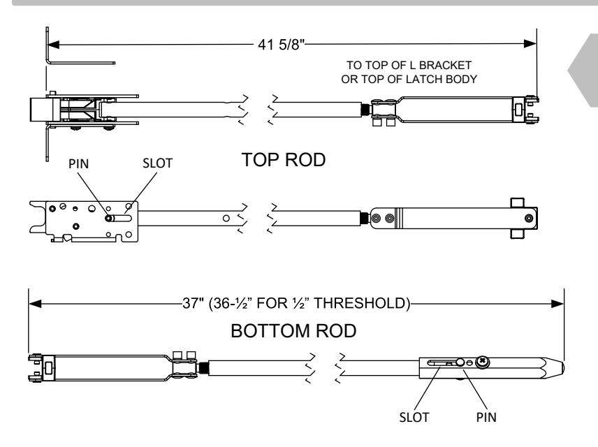
3. ADJUST RODS
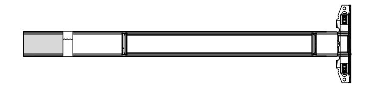
When measuring, be sure length is in the collapsed pin position as shown.
TOP ROD LENGTH: Measure from top of door to device centerline. Subtract 2 1/ 4".
Typical 7' Door: 41 5/8" (43 7/8" - 2 1/4" = 41 5/8")
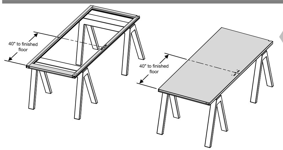
BOTTOM ROD LENGTH: 37" if device is installed 40" above the finished floor.
20685_A (639409 Rev2)
PD27/28/29/30 INSTALLATION INSTRUCTIONS CVR DEVICE

4. INSTALL LATCHES IN DOOR
- Slide latch/rod assemblies into the door. Slide bottom latch into door installed in housing.
- Fasten with #8-32 screws.
**IMPORTANT NOTE**
| Maximum cut: | ||||
|---|---|---|---|---|
| Panic | Fire | Alarm | MLR | |
| 36" Device | 6" | 8" | 2" | 3" |
| 48" Device | 12" | 14" | 8" | 9" |

5. SIZE DEVICE
- Standard lengths are for 36" or 48" door. Device must be cut for other lengths.
- Mark length with tape length equals device size minus desired door size (for 30" door = cut 6" off 36" device) ensuring a square cut.
PD27/28/29/30 INSTALLATION INSTRUCTIONS CVR DEVICE

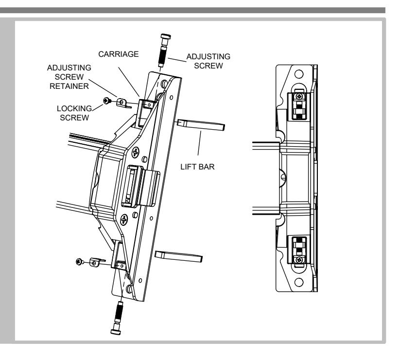
6. INSTALL CVR LIFT BARS
- Adjusting screw and retainer factory installed without lift bars.
- Remove adjusting screw retainers and adjusting screws.
- Insert lift bar into carriage from back side of device.
- Thread adjusting screw into lift bar through carriage until the lift bar is centered on threads.
- Insert adjusting screw retainer into the notched area of the adjusting screw.
- Install/tighten #4-40 locking screw.
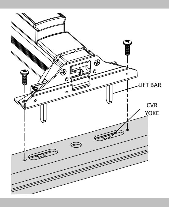

7. INSTALL DEVICE
- Install device and trim with 1/4-20 screws from pack #639043.
- Verify lift bars engage into CVR yokes for both top and bottom latches.
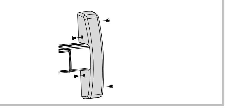
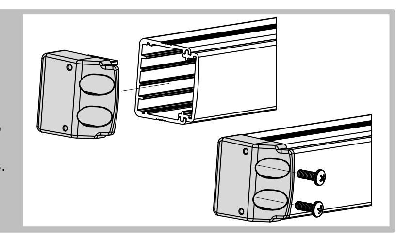
8. INSTALL END CAP
- Slide end cap into rail. Ensure rail is square to door. Mark centers of slots.
- Remove end cap, drill holes according to correct device/trim template.
- Reinstall end cap and fasten with screws.
PD27/28/29/30 INSTALLATION INSTRUCTIONS

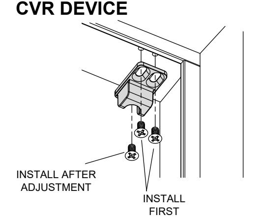
9. INSTALL TOP STRIKE
- Install strike using two #10-24 flat head screws from pack #639054.
- With door installed, adjust strike to desired door free play. Recommended is minimum of 1/16".
- Install third flat head locking screw by drilling and tapping for #10-24 after final adjustment is achieved.
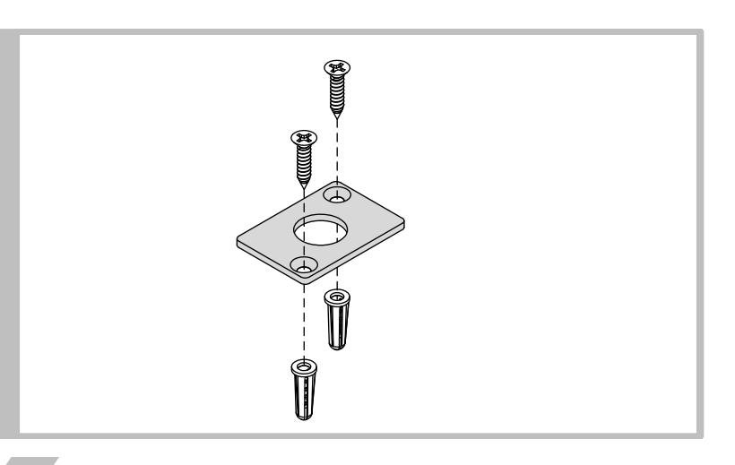
10. INSTALL BOTTOM STRIKE
- Close door and mark center of bottom bolt on floor.
- Center strike and mark location of screw holes.
- Drill strike hole and anchor holes according to template.
- Install plastic anchors into floor.
- Install strike using two flat head screws.
ADJUSTING SCREW LOCKING SCREW CARRIAGE LIFT BAR To Adjust: On device chassis/ head, loosen locking screw & rotate adjusting screw
11. FINE ADJUST RODS
TOP ROD ADJUSTMENT: Open door by depressing pushbar & releasing. If carriage drops more than 1/8", top lift bar must be adjusted downward (Counterclockwise). If door is difficult or unable to be opened, top lift bar must be adjusted upwards (Clockwise).
BOTTOM ROD ADJUSTMENT: Check bottom rod adjustment by opening door. With door opened and pushbar released, lower bolt should be 1/16" above strike.
12. INSTALL HEAD COVER
- Slide head cover onto exit device
- Install 4 mounting screws