Command Access PD27 SVR Installation Instructions
Open the original PDF document
View PDF

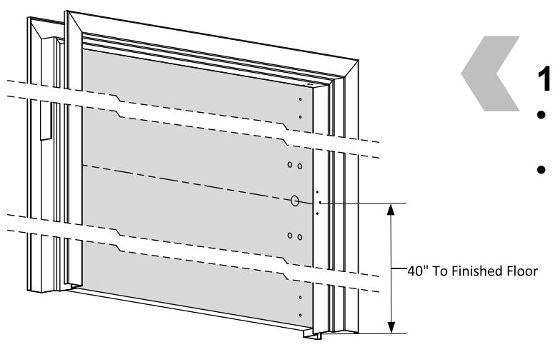
1. PREPARE DOOR
- Prepare door, frame and floor or threshold according to template.
- Refer to trim template if installing trim.
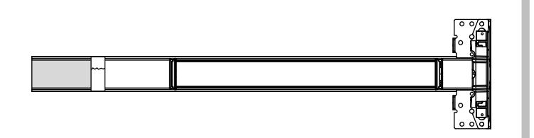
2. SIZE DEVICE
- Standard lengths are for 36" or 48" door. Device must be cut for other lengths.
- Mark length with tape length equals desired door size subtracted from device size (for 30" door = cut 6" off 36" device) ensuring a square cut.
| Maximum cut off length: | |||||
|---|---|---|---|---|---|
| Panic | Fire | Alarm | MLR | ||
| 36" Device | 6" | 8" | 2" | 3" | |
| 48" Device | 12" | 14" | 8" | 9" | |
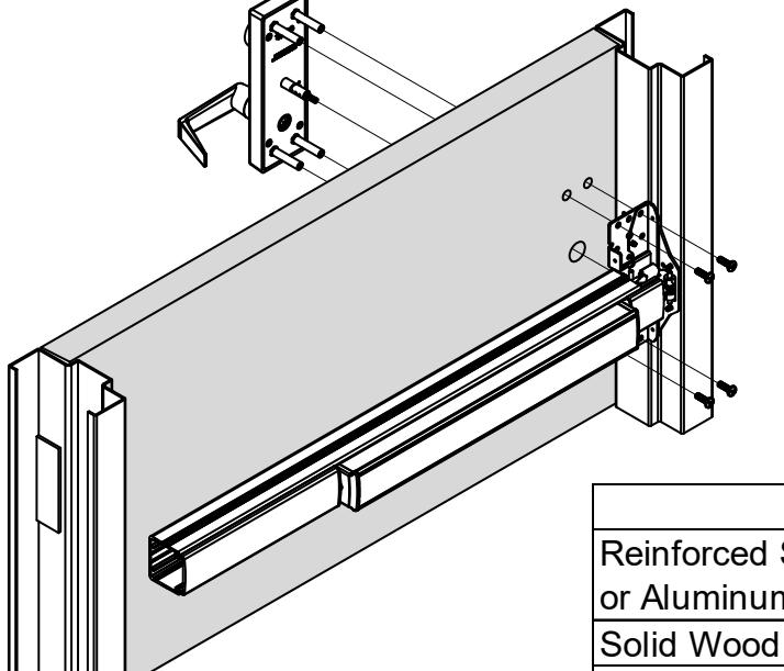

- Install device and trim with chassis/case screws (2 or 4 screws depending on device and trim type).
- Device can be surface mounted to the door, optional sex nuts are available, device is through bolted if using trim.
- VF devices must be through bolted on wood or composite doors.
| Mounting Options: | |||
|---|---|---|---|
| Reinforced Steel | Surface Mount: Drill/Tap push side for 1/4-20 | ||
| or Aluminum Door | |||
| Solid Wood Door | Drill 1/8" Pilot Hole for #10 Wood Screw | ||
| All Others | Use optional Sex Bolts. Drill push side with | ||
| 9/32" drill bit. Drill pull side with 3/8" drill bit. | |||

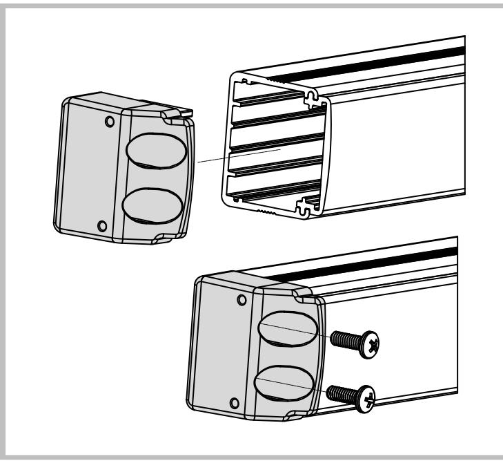
4. INSTALL END CAP
- Slide end cap into rail. Ensure rail is level. Mark the slots.
- Remove end cap and prepare holes using the chart from Step 3.
- Reinstall end cap and fasten with screws.
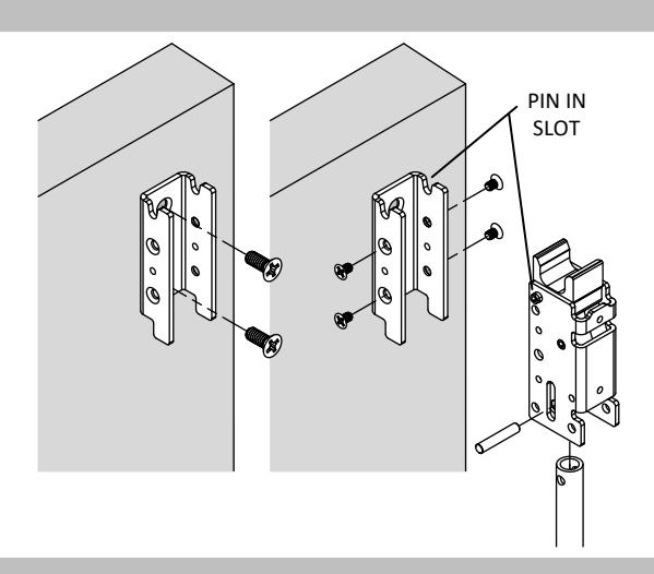

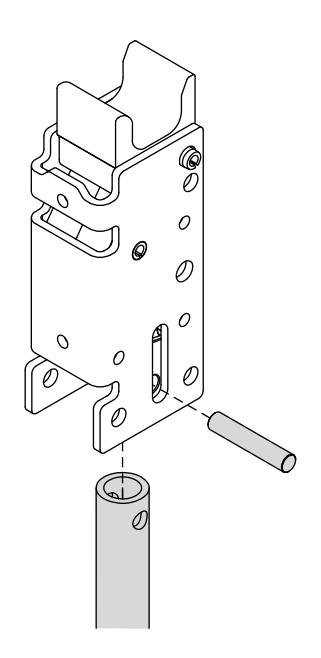
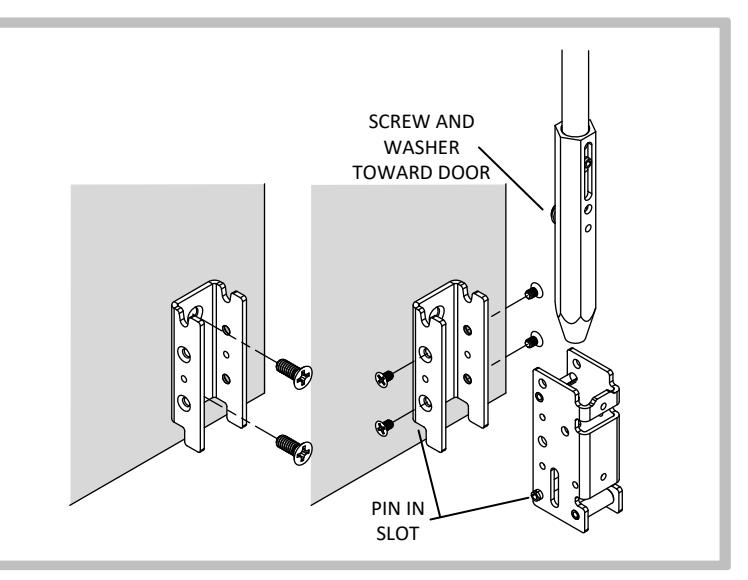
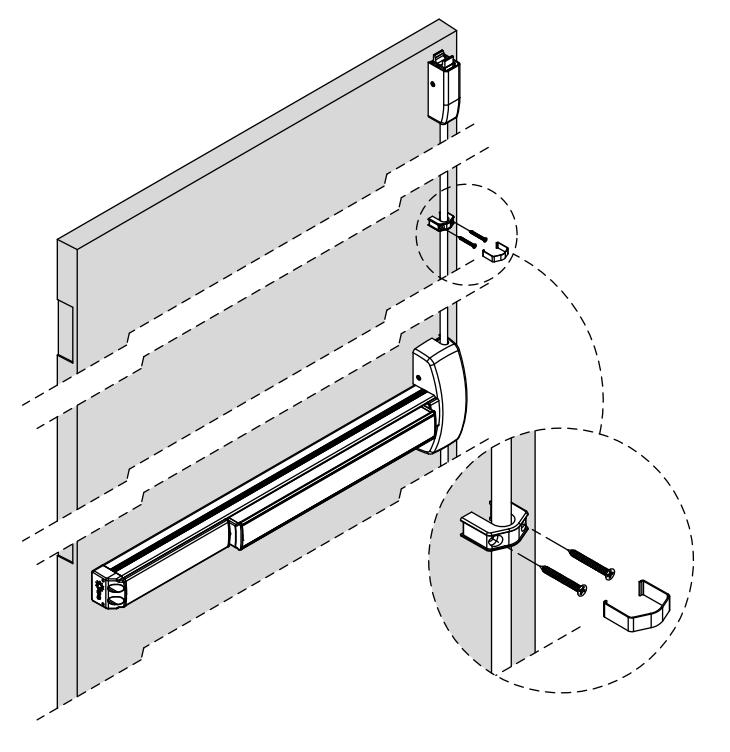
5. INSTALL TOP LATCH
- Install mounting bracket to door with two 1/4-20 x 5/8" flat head screws.
- Install rod using pin as shown.
- Hang latch from pin in mounting bracket, secure latch using the four #8-32 x 1/4" flat head screws.
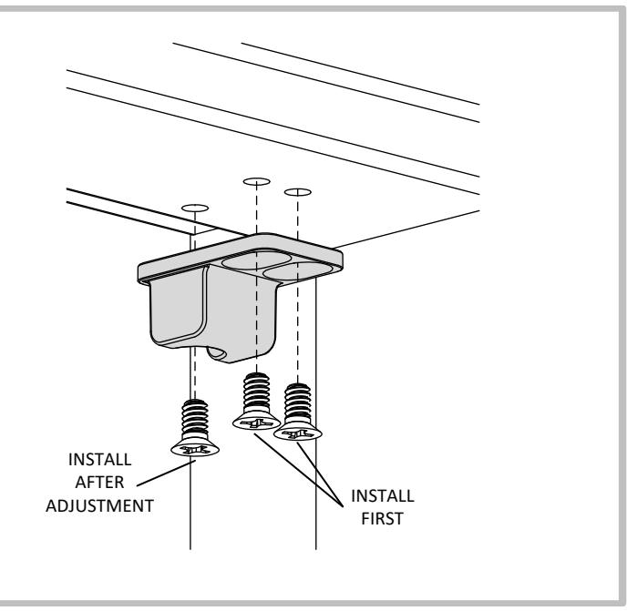
6. INSTALL TOP STRIKE
- Install strike using two #10-24 flat head screws.
- Adjust strike to secure door.
- Install third flat head locking screw by drilling and tapping for #10-24 after final adjustment is achieved.

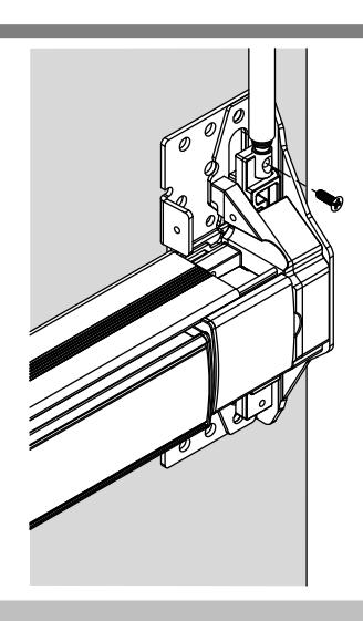

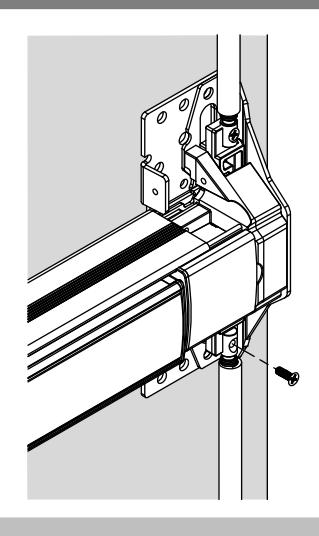
7. ADJUST TOP ROD
- Ensure top latch is in the unlatched position by lifting up then releasing the rod. Rod should remain up.
- Depress the push bar and adjust the top rod connector by threading it in or out of the rod until it lines up with the screw hole in the device head. Do not manually lift the carriage. Secure rod with #8-32 flat head screw.
8. INSTALL BOTTOM LATCH
*Omit this step for LBR devices.
- Install mounting bracket to door with two 1/4-20 x 5/8" flat head screws.
- Install latch into the mounting bracket, ensuring the long pin is in the designated area, using the four #8-32 x 1/4" flat head screws.
- Install rod and bottom bolt into latch body ensuring screw and washer are facing door.
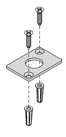

9. INSTALL BOTTOM STRIKE
*Omit this step for LBR devices.
- Close door and mark center of bottom bolt on floor.
- Center strike and mark location of screw holes.
- Drill strike hole and anchor holes according to template.
- Install plastic anchors into floor.
- Install strike using two flat head screws.


10. ADJUST BOTTOM ROD
*Omit this step for LBR devices.
- Ensure top latch is in the unlatched position.
- While the top latch is in the unlatched position adjust the bottom rod until it clears the strike by approximately 1/8". Install #8-32 flat head screw.
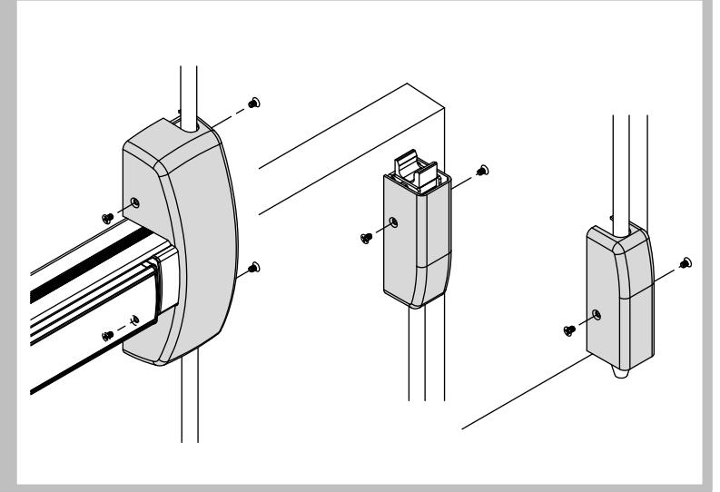
11. INSTALL HEAD COVER AND LATCH COVERS
- Install the headcover. Secure with four #8- 32 x 1/4" flathead screws.
- Install latch covers, secure with two #8- 32 x 1/4" flathead screws each.

12. INSTALL ROD GUIDES
- Measure distance between latches and chassis head cover. Mark the centers.
- Using the rod guide as a template, mark the hole locations making sure the rod is centered in the guide and the guide is level.
- Predrill hole locations with a 1/8" drill bit.
- Install rod guides using the #8 flat head screws from screw pack 639045.
- Snap the rod guide cover over the rod guide.


CUT TOP ROD
Cutting is not required for standard 7', 8' or 10' doors.
1. Calculate top rod cut.
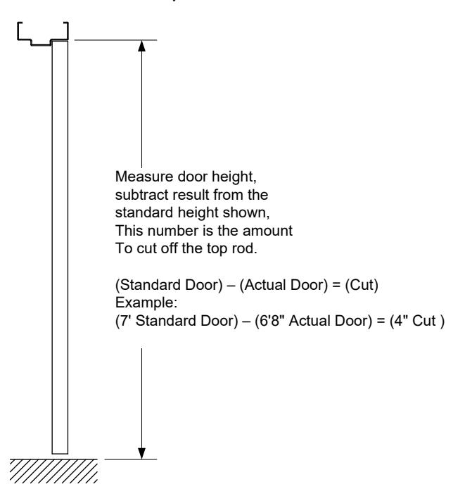
| *Standard Door Heights | |||
|---|---|---|---|
| Shorter Rod (37-3/8") | 7' (84") | ||
| Longer Rod (49-3/8") | 8' (96") | ||
| Shorter Rod with 3' Extension | 10' (120") | ||
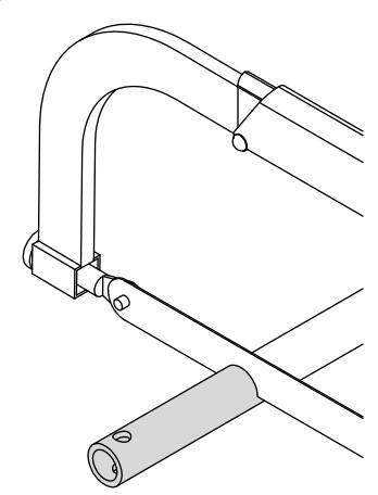
2. Cut rod.
**Cut only the cross drilled end.**
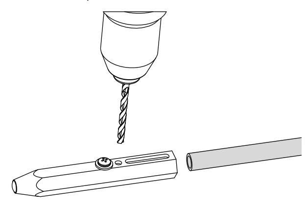
3. Drill new 3/16" hole.
*Use the bottom latch bolt as a drill guide for new hole. If no bottom latch is present drill hole centered 1/4" from end of rod.
4. Install rod in top latch.