Command Access PD27 Rim Installation Instructions
Open the original PDF document
View PDFPD27/28/29/30 INSTALLATION INSTRUCTIONS RIM DEVICE


1. PREPARE DOOR
- Prepare door and frame according to template.
- Refer to trim template if installing trim.
2. SIZE DEVICE
- Standard lengths are for 36" or 48" door. Device must be cut for other lengths.
- Mark length with tape length equals device size minus desired door size (for 30" door = cut 6" off 36" device) ensuring a square cut.
| Maximum cut off length: | |||||
|---|---|---|---|---|---|
| Panic | Fire | Alarm | MLR | ||
| 36" Device | 6" | 8" | 2" | 3" | |
| 48" Device | 12" | 14" | 8" | 9" | |
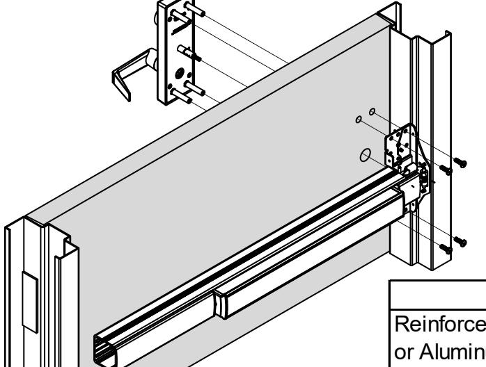

3. INSTALL DEVICE
- Install device and trim with 1/4-20 screws from pack #639043.
- Device can be surface mounted to the door, optional sex nuts are available, device is through bolted if using trim.
| Mounting Options: | |||
|---|---|---|---|
|
Reinforced Steel
or Aluminum Door |
Surface Mount: Drill/Tap push side for 1/4-
20 |
||
| Solid Wood Door | Drill 1/8" Pilot Hole for #10 Wood Screw | ||
| All Others |
Use optional Sex Bolts. Drill push side with
9/32" drill bit. Drill pull side with 3/8" drill bit. |
||
PD27/28/29/30 INSTALLATION INSTRUCTIONS RIM DEVICE

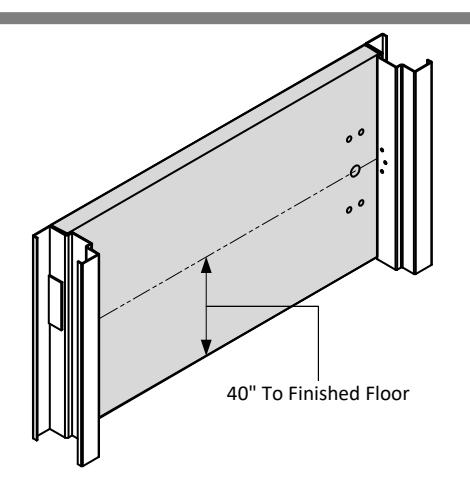
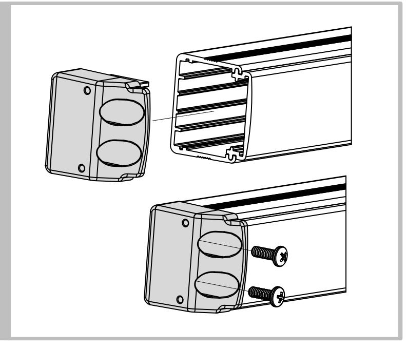
4. INSTALL END CAP
- Slide end cap into rail. Ensure rail is level. Mark the centers of the slots.
- Remove end cap then drill holes using the chart from Step 3.
- Reinstall end cap and fasten with screws.
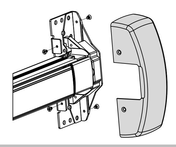

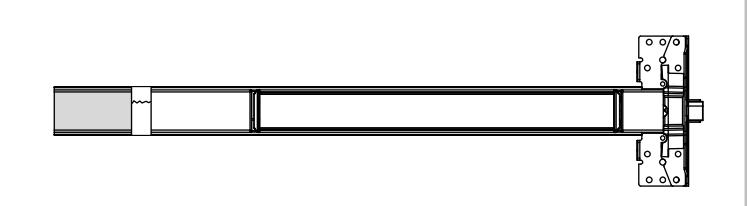
5. INSTALL HEAD COVER
- Slide head cover onto exit device
- Install 4 mounting screws
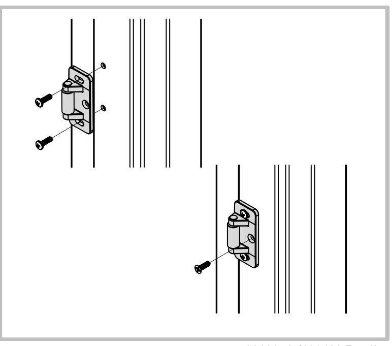
6. INSTALL STRIKE
- Install strike with roller toward door face using two #10-24 pan head screws.
- Adjust strike to secure door.
- Install flat head locking screw by drilling and tapping for #10-24 after final adjustment is achieved.