Camden Waterproof Keypad CM-550SK-V2 Installation Instructions
Open the original PDF document
View PDF

Door Activation Devices
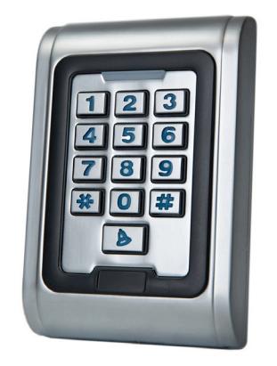
CM-550SK-V2 Waterproof Keypad
INSTALLATION INSTRUCTIONS
THIS PACKAGE INCLUDES:
(2) 0.15" x 1.06" (4mm x 27mm) Self-tapping screws (1) 1N4007 Two-electrode valve
(2) 0.23" x 1.2" (6mm x 30mm) Rubber plug
(1) 0.78" x 2.4" (20mm x 60mm) Star screw driver
1. DESCRIPTION
The CM-550SK is a single door standalone keypad with a Wiegand input/output interface. It is suitable for mounting either indoors or outdoors in harsh environments. It is housed in a strong, sturdy and vandal proof Zinc Alloy electroplated case. The electronics are fully potted so the CM-550SK is waterproof and conforms to IP68.
The CM-550SK supports up to 2000 users with a 4~6 digit PIN. These features make CM-550SK an ideal choice for door access for commercial and industrial applications such as factories, offices, warehouses, laboratories, banks and prisons.
2. FEATURES
- Waterproof, conforms to IP68
- Strong Zinc Alloy Electroplated anti-vandal case
- Full programming from the keypad
- 2,000 users
- PIN length 4~6 digits
- Backlit keypad
- Wiegand input & output
- One programmable Relay output, NO, NC, COM
- Adjustable Door Output time, Alarm time, Door Open time
- Very low power consumption (< 60mA)
- Easy to install and program
- Built in light dependent resistor (LDR) for anti-tamper
- Built in buzzer
- Red, Yellow and Green LEDs display the working status
- 12 VDC +/- 10%
- Three-year warranty
3. SPECIFICATIONS
| Model | CM-550SK-V2 |
|---|---|
| Voltage | 12 VDC +/- 10% |
| IP rating | 68 |
| Idle Current | 25mA |
| Contact Type | (1) Form 'C' |
| Contact Rating | 1 Amp@30VDC |
| Alarm Output Load | 1 Amp@30VDC |
| Ring Bell Load | 1 Amp@30VDC |
| Card Read Distance | 1.75" (40Mm) Max |
| Card Frequency | 125KHz, EM and HID |
| Keypad Format | 4 bit, 8 bit and 26 Bit |
| Operating Temp. | -49°F to 113°F (-45°C to 55°C) |
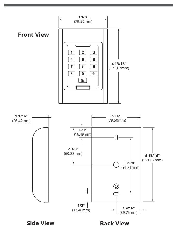
| Dimensions |
4 13/16" H x 3 1/8" W x 1 1/16" D
(121.67mm x 79.5mm x 26.42mm) |
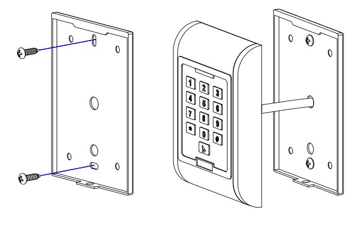
4. INSTALLATION
- 1. Remove the back cover from the keypad using the supplied special screw driver.
- 2. Drill 2 holes on the wall for the self tapping screws and 1 hole for the cable.
- 3. Put the supplied rubber plugs into the two holes.
- 4. Fix the back cover firmly on the wall with 4 flat head screws.
- 5. Thread the cable through the cable hole.
- 6. Attach the keypad to the back cover.
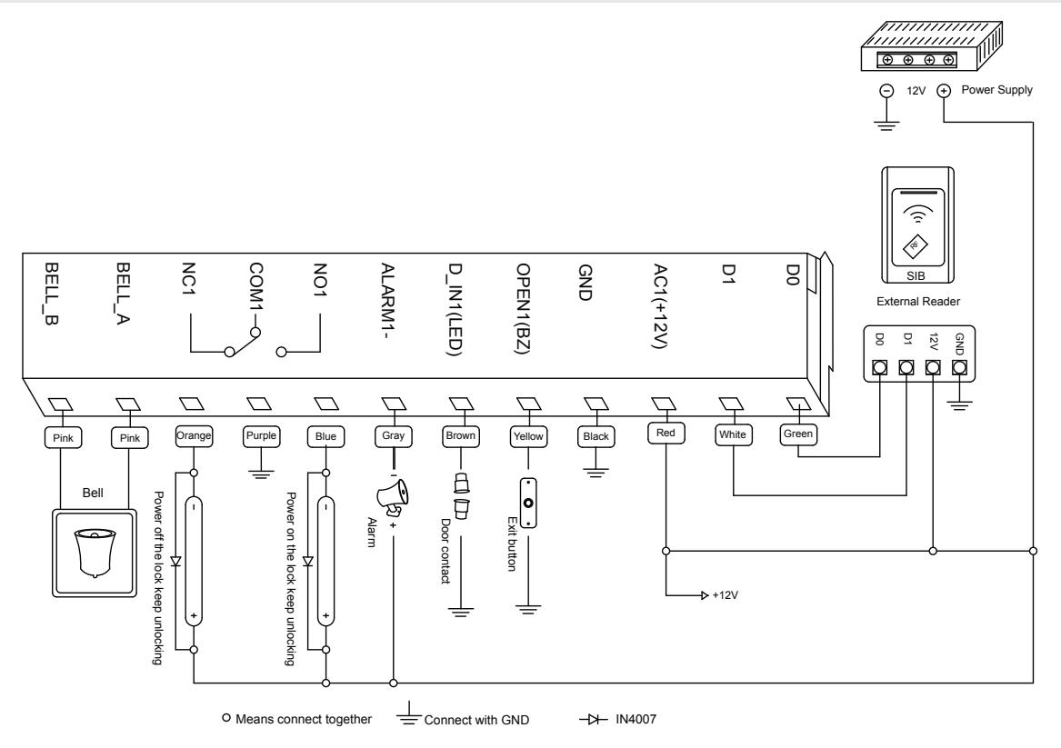
5. WIRING
| No. | Marks | Colour | Description |
|---|---|---|---|
| 1 | BELL_A | Pink | Doorbell button |
| 2 | BELL_B | Pink | Doorbell button |
| 3 | D0 | Green | Wiegand output D0 |
| 4 | D1 | White | Wiegand output D1 |
| 5 | ALARM | Gray | Alarm |
| 6 | OPEN | Yellow | Request to Open (BUZ) |
| 7 | D_IN | Brown | Door Contact (LED) |
| 8 | DC | Red | Power IN |
| 9 | GND | Black | Ground |
| 10 | NO | Blue | Relay NO |
| 11 | COM | Purple | Relay Com |
| 12 | NC | Orange | Relay NC |
6. SOUND AND LIGHT INDICATION
| Operation | LED Colour | Buzzer |
|---|---|---|
| Standby | Red Flash | |
| Press Key | DI | |
| Read Card | Green | Di |
| Door 1 Open | Green | Di |
| Door 2 Open | Green Flash | Di |
| Operation Successful | Green | Di |
| Operation Failed | Di-Di-Di | |
| PIN inputting | Red | |
| Pin Reading | Red | |
| Under Menu | Red | |
| Under Setting | Orange | |
| Manager Card Enter | Orange | Di-Di |
| Manager Card Exit | Red Flash | Di |
| Alarm | Red Quick Flash | Alarm |
7. QUICK PROGRAMMING GUIDE
7.1 Administrator Setting
| Standby | Master Code | Menu | Setting | Remarks | Functions |
|---|---|---|---|---|---|
| Red Flash | Red | Red | Orange | ||
| * | Master Code # | 00 |
New Master Code #,
Repeat New Master Code # (Note: Code length: 6-8 digits) |
Factory Default:
999999 |
Change the Master Code |
| 05 | Anti-duress PIN# | Anti-duress PIN | |||
| 07 | 0000# | Delete All Users | |||
| 51 | Master open |
7.2 User Setting
| Standby | Master Code | Menu | Setting | Remarks | Functions |
|---|---|---|---|---|---|
| Red Flash | Red | Red | Orange | ||
| * | Master Code # | 11 | User ID number #, PIN # |
Users can be added
continuously without exiting programming mode |
To add PIN users |
| 12 | User ID Number # |
Users can be added
continuously without exiting programming mode |
To Delete Users | ||
| 13 | 2 # | Default 2 | Entrer by Card/PIN | ||
| 14 | 0-99 # | Default 5 | Set Door Relay Time | ||
| 0 # | Ready Setting-Pulse Mode | ||||
| 15 | 1 # | Default 0 | Ready Setting-Toggle Mode | ||
7.3 System Setting
| Standby | Master Code | Menu | Setting | Remarks | Functions |
|---|---|---|---|---|---|
| Red Flash | Red | Red | Orange | ||
| * | Master Code # | 30 | 0-15 # | Default 0 | To Set Facility Code |
| 0 # | This setting is not | Wiegand Reader | |||
| 31 | 1 # |
affected by resetting
to factory default. |
Standalone for Single Door | ||
| 33 | 0-2 # |
This setting is not
affected by resetting to factory default. |
To set keypad
transmission format 0=26 bit weigand 1=4 bit burst 2=8 bit burst |
||
| 34 | 1-3 # | Default 1 | To set alarm time in minutes | ||
|
0 #
35 1 # Default 0 |
Normal mode | ||||
| Lock out mode | |||||
| 2 # | Alarm mode |
7.4 User Optional Setting
| Standby | Master Code | Menu | Setting | Remarks | Functions |
|---|---|---|---|---|---|
| Red Flash | Red | Red | Orange | ||
| * | Master Code # | 41 | 0 # | Buzzer is turned off, except while in programming mode | |
| 1 # | Default 1 | Buzzer will sound during key presses | |||
| 42 | 0 # | Disable keypad backlighting | |||
| 1 # | Enable keypad backlighting | ||||
| 0 # | LED Light Disable while in stand-by | ||||
| 43 | 1 # | Default 1 | LED flashes while in stand-by |
Notes:
- 1. Master code must be 6-8 digits.
- 2. Anti-duress PIN must be 8 digits.
- 3. User PIN is 4-6 digits.
- 4. The user ID number is any number from 1-2000
- 5. Door open time is 0-99 second, 0=50mS.
- 6. While operating the keypad, pressing # means to confirm the input digits, in operation of a cycle adding or deleting PIN code, pressing # means to end the cycle operation and back up the operation; pressing * means to exit the operation.
- 7. Keypad Wiegand modes are set at the factory to 26 bit. If the output format is changed through programming, the changes are not affected by a reset to factory defaults.
8. ADMINISTRATOR SETTING
| 8.1 Administrator Setting | ||||
|---|---|---|---|---|
| Administrator setting on keypad | Press * master code # factory default: 999999 | |||
| Change the master code | Press 00 new code # repeat new master code # | |||
| Note: Master code length: 6-8 digits | ||||
| 8.2 Set Anti-Duress PIN | ||||
| Set anti-duress PIN | Press 05 8-digit duress PIN # (Zone 1) | |||
| 8.3 Delete All Users | ||||
| Delete all users | Press 07 0000 # | |||
| 8.4 Activate the Lock Output While in Programming Mode | ||||
|---|---|---|---|---|
| Activate the lock output while in programming mode | Press * master code # factory default: 999999 | |||
| Press 51 | ||||
| Note: The relay will operate for the relay on time. | ||||
| 8.5 Users Setting | ||||
| Note: ID number is 1-4 digits, the range is 1-2000, 1, 01, 001, 0001, all these mean ID number 1 | ||||
| Use ID number and PIN to add user | Press 11, ID number # PIN #, ID number #PIN #, # | |||
| Note: The PIN is any 4-6 digits, exept 1234 which is reserved. | ||||
| 8.6 Set Door Relay Time | ||||
| Set door relay time | Press 14, 0-99, # | |||
| Note: 0-99 is to set the door delay time 0-99 seconds, factory default is 5 seconds. | ||||
| 8.7 Set Relay Mode | ||||
| Relay setting-pulse mode | Press 15, 0, # | |||
| Relay setting-toggle mode | Press 15, 1, # | |||
| 8.8 System Setting | ||||
| To set facility code | Press 30, 0-15, # | |||
| Note: Code should be 0-15, factory default setting: 0 | ||||
| Wiegand Reader | Press 31, 0, # | |||
| Stand alone for single door (factory default setting) | Press 31, 1, # | |||
| 8.9 Setting Keypad Transmission Format | ||||
| Setting keypad transmission format | Press 33, 0-2, # | |||
| Note: Keypad transmission format is 0 1 2, factory default is 0; not affected by resetting to factory default. | ||||
| 8.10 Setting Alarm Time | ||||
| Setting alarm time | Press 34, 1-3, # | |||
| Note: Factory default is 1 minute, not affected by resetting to factory default. | ||||
| 8.11 Setting Safe Mode | ||||
| Normal mode (factory default) | Press 35, 0, # | |||
| Lock out mode | Press 35, 1, # | |||
| Note: If an invalid card or wrong PIN is input 10 times in 10 minutes, user will be locked out for 10 minutes. | ||||
| Alarm mode | Press 35, 2, # | |||
| Note: If an invalid card or wrong PIN is input 10 times in 10 minutes, external alarm and built-in buzzer will sound. | ||||
| 8.12 User Optional Setting | ||||
| Setting keypad tone OFF or ON | Press 41, 0, # OFF | |||
| Press 41, 1, # ON (Default) | ||||
| 8.13 Setting Keypad Backlight | ||||
| Disable keypad backlight | Press 42, 0, # | |||
| Enable keypad backlight | Press 42, 1, # | |||
| Automatic mode (factory default setting) | Press 42, 2, #, Keypad will illuminate when a key is pressed. | |||
| 8.14 Setting LED Light (Standby Status) | ||||
| Disable LED light | Press 43, 0, # | |||
| Flash LED light (factory default setting) | Press 43, 1, # | |||
9. USER OPERATION
9.1 Entry PIN Mode
- Press PIN (4 to 6 digits), #, lock will be unlocked.
9.2 Relay Mode
- Relay setting-pulse mode.
- Every time a valid card/tag read or PIN input, the relay will operate, for the pre-set relay pulse time.
- Relay setting-toggle mode.
- Every time a valid PIN is entered, the relay changes state, which will not turn back until a valid PIN is entered again.
9.3 Modify User PIN (no need to enter programming)
- Press ID number #, old PIN #, new PIN #, new PIN #
10. ALARM FUNCTION
10.1 Anti-Tamper Alarm
- If the device is disassembled illegally, the buzzer and the external alarm will operate.
10.2 Door Contact Alarm
- When connected with door contact: if the door is opened illegally, the buzzer and the external alarm will operate.
10.3 The Anti-Duress Alarm
- Input 8-digit PIN and press #
- Corresponding lock will open. At the same time, the external alarm will operate, but the device buzzer will not operate.
10.4 Remove Alarm
- Input master code, then alarm will be removed. The alarm will time out automatically after 1 min.
11. MULTI-WORKING MODE
There are 3 working modes with this device.
- 1. Wiegand Reader.
- 2. Standalone for single door.
- 3. Anti-passback for single door.
The factory default is Standalone for single door (we can change the default model according to customer order). User can modify the working mode when the device reset to factory default, the setting is still valid.
11.1 Wiegand Reader Mode
In this mode, the access control works as a reader, connected with the common access controller.
It has the following function:
- Modify master pin
- Set facility code
- Set the keypad transmission format
- Set optional setting
- Anti-Tamper alarm
When LED level is low, indicator light (LED) will turn into green, after 30 seconds or LED level riding, LED will go back to normal.
When BZ level is low, the buzzer will beep, after 30 seconds or BZ level rising, the buzzer will go back to normal.
When used as the reader, the keypad transmits in Wiegand format, the output data is shown by the low level of D0&D1 wire:
D0: Low level means 0, green wire D1: Low level means 1, white wire
The pulse width of low level is 100uS, bit period is 1.6mS.
Keypad transmission can be set in the following 3 modes (modes can be set by user).
Model 0: Virtual Card Number
The reader will transmit the PIN data when it receives the last key (#) press after PIN code
Format: Decimal card number with 10 digits, Facility code (1st-4th digit) + PIN Code (5-10th digit)
Facility code is any digit between 0-15, PIN code is 4-6 digits.
Example: facility code: 15 PIN code: 999999
Press 999999#, then output format will be 0015999999
Model 1: 4 Bit
The output data is provided in the following format after every key is pressed:
| Key | Output in Hex | Output in Binary |
|---|---|---|
| 0 | 0 | 0000 |
| 1 | 1 | 0001 |
| 2 | 2 | 0010 |
| 3 | 3 | 0011 |
| 4 | 4 | 0100 |
| 5 | 5 | 0101 |
| 6 | 6 | 0110 |
| 7 | 7 | 0111 |
| 8 | 8 | 1000 |
| 9 | 9 | 1001 |
| * | A | 1010 |
| # | B | 1011 |
INSTALLATION INSTRUCTIONS
Model 2: 8 Bit
The output data is transmitted in the following format after every key is pressed:
| Key | Output in Hex | Output in Binary |
|---|---|---|
| 0 | 0 | 11110000 |
| 1 | 1 | 11100001 |
| 2 | 2 | 11010010 |
| 3 | 3 | 11000011 |
| 4 | 4 | 10110100 |
| 5 | 5 | 10100101 |
| 6 | 6 | 10010110 |
| 7 | 7 | 10000111 |
| 8 | 8 | 01111000 |
| 9 | 9 | 01101001 |
| * | A | 01011010 |
| # | B | 01001011 |
11.2 Stand alone for single door
In this mode, the device supports connecting external card reader for exiting door. The users of Zone 1 or external can open the door by valid card or PIN.
11.3 Anti-Passback for single door
In this mode, this unit install outside is for entering door, external reader inside for exiting door, the users can only enter door when read valid card on the machine, and exit from the inside external reader. If without the entering record.
Note: this is only for card users of Zone 1, PIN users of Zone 1 an all users of Zone 1 are invalid.
12. DIAGRAMS FOR WORKING MODES
DC12V common power Mode Standalone for single door diagram Mode Anti-passback for single door diagram
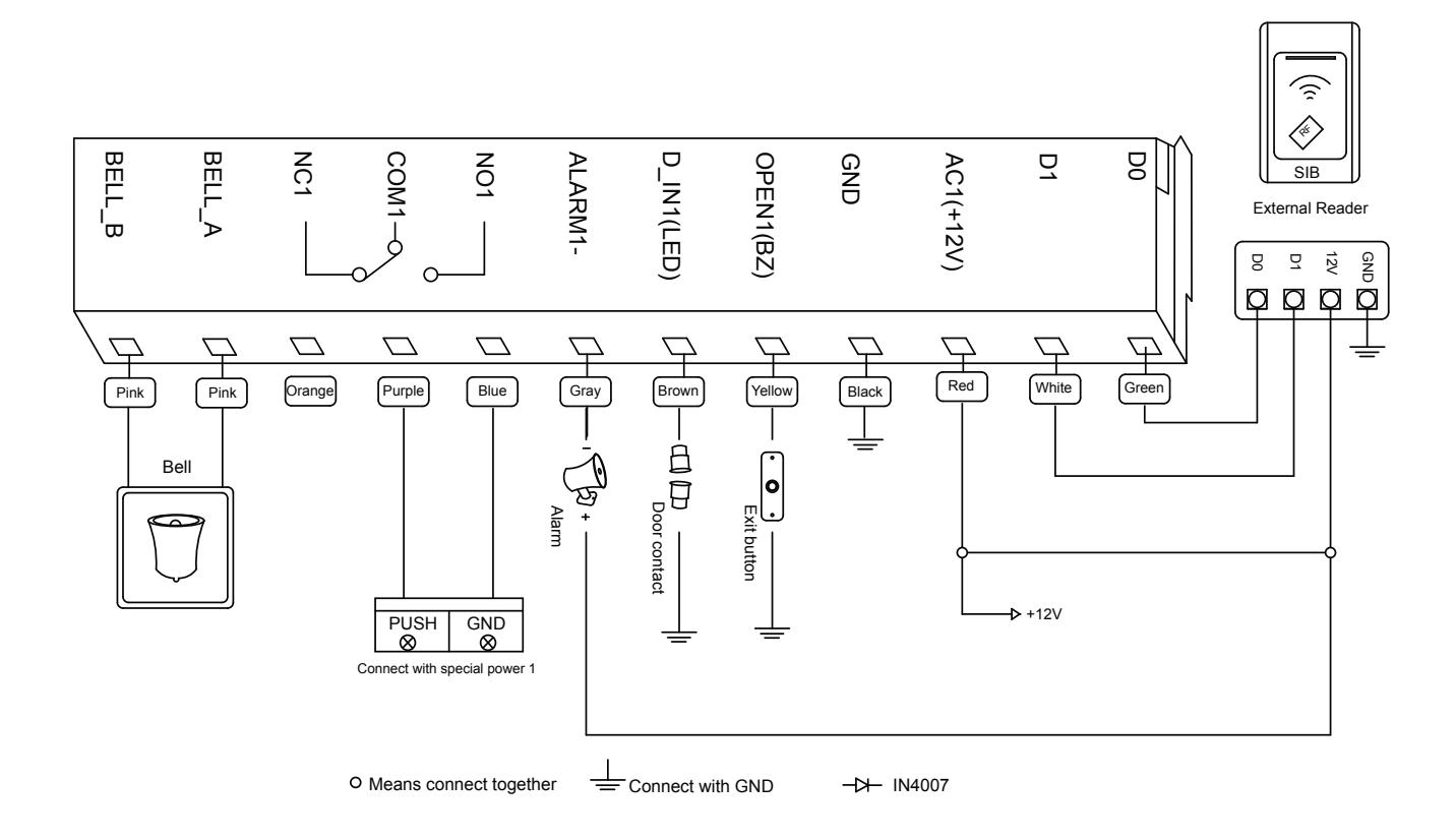
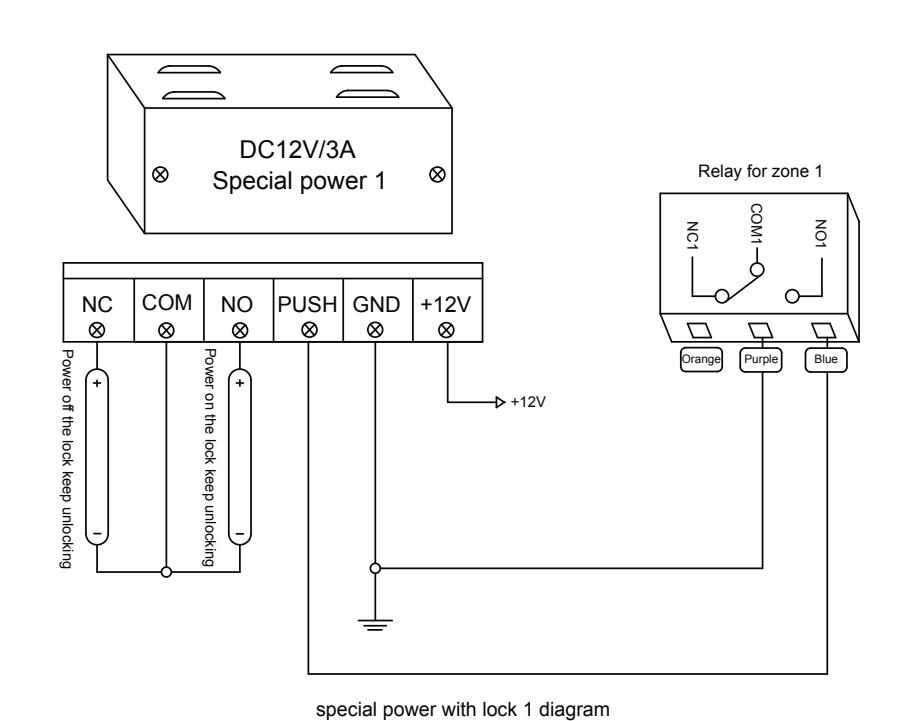
DC12V special power Mode Standalone for single door diagram Mode Anti-passback for single door diagram
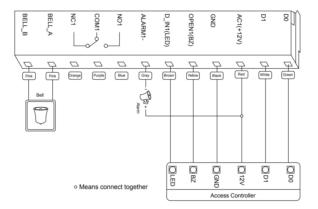
Mode Wiegand reader diagram
13. SIMPLE TROUBLESHOOTING
| Code | Fault | Fault Cause | Solutions |
|---|---|---|---|
| 1 | Problem in PIN setting |
1. PIN is not standard
2. Set Password at reader mode |
1. PIN shouldn't be 1234
2. PIN is 4 to 6 digits 3. Don't set PIN at reader mode |
| 2 | PIN can't open door |
1 use PIN 1234
2 entry mode setting |
1. 1234 is original PIN, can't open the door,
should be modified as other PIN 2. Set open mode as entry by card or PIN. |
| 3 | Alarms at normal condition |
During installation, light leak
under bottom |
During installation, device should be close to wall |
| 4 | |||
| 5 | Keypad light is not bright |
Mode of keypad light setting
is wrong |
1. Set keypad light as shine or auto
2. Under auto mode, light shine after press keypad, delay 30 seconds |
| 6 | Can't enter master mode | Forget master code |
Reset to Factory Default, master code will be
999999, only installer data is restored, user data will not be affected |
14. RESET TO FACTORY DEFAULT
- a. Disconnect power from the unit.
- b. Press and hold # key whilst powering the unit back up.
- c. On hearing two "Di" release # key, system is now back factory settings.
Note: Only installer data is restored, user data will not be affected.