Camden Surface and Flush Round Escutcheons CM49 Manual
Open the original PDF document
View PDF

CM-49 4 1/2" Switch Escutcheon Mounting Instructions
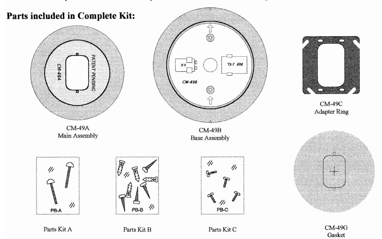
The CM-49 may be ordered as a Complete Kit, or as individual components.
Mounting Configurations:
The CM-49 Complete Kit enables a 4 ½" round switch to be installed in any in-wall electrical box, or to be surface mounted. The chart below show the possible mounting configurations and components required. Refer to diagram above for parts identification.
| COMPONENTS > MOUNTING |
MAIN
CM-49A |
BASE
CM-49B |
ADAPTER
CM-49C |
GASKET
CM-49G |
PARTS
KITS |
||
|---|---|---|---|---|---|---|---|
| A | В | C | |||||
|
1. Surface Mount to a solid /
hollow Wall (no Box) |
• | ~ | Not required | Optional | ~ | ~ | |
| 2. Mount to a single-gang in-wall electrical box | • | Not required | Not required | Optional | • | ||
| 3. Mount to a double-gang in-wall electrical box | • | Not required | ~ | Optional | • | • | |
| 4. Mount to a '4 x 4' in-wall electrical box | • | Not required | > | Optional | • | • | |
| 5. Mount to Glass | Not recommended due to safety issues | ||||||
| 6. Mount to a surface box | Not recommended due to incompatibility | ||||||
| 7. Mount to a "Wallgrabber" | Not recommended due to insufficient strength | ||||||
Installation Instructions
Surface Mount (Configuration #1)
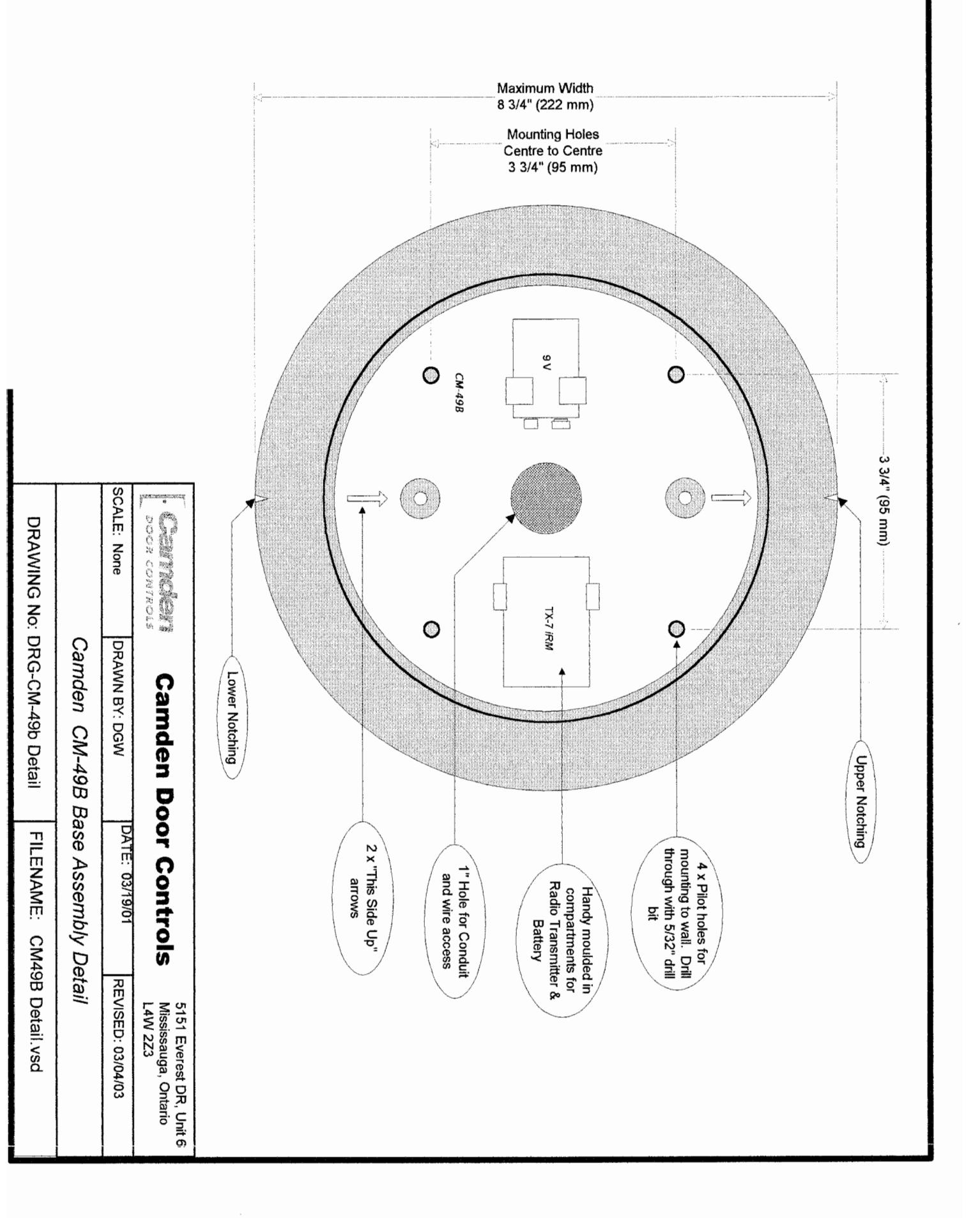
- 1. Locate the 4 pilot holes in the base assembly (CM-49B). They are not drilled all the way through so that you may drill your own holes to match existing layout or, site conditions. Drill 4 x 5/32" (minimum) holes through base.
- 2. Mark an "X" on the wall at the desired mounting height. Using a level, draw a vertical pencil line at least 5" above and below your "X".
- 3. Hold the base assembly on the wall with the "X" visible though the centre hole, and the arrows pointing up. Line up the top & bottom leveling notches with the vertical pencil line. Mark the drilling locations with a pencil or centerpunch.
- 4. Remove the base assembly and drill holes in wall. Insert the appropriate wall fasteners.
- 5. If you wish to use the supplied weather gasket, remove the backing paper, and attach to rear of CM-49B. If hardwiring the CM-49 you will notice a perforated slot opening in the centre of the gasket to accommodate wiring. Alternatively, a channel in the perimeter allows a bead of caulking for mounting to rough surfaces.
- 6. Fasten the base assembly to the wall with supplied screws.
- 7. If using Radio controls, we have molded-in compartments to hold the transmitter and battery securely. Install transmitter, battery and pull switch wiring out full length.
- 8. Line up part A over part B, and partially screw in the two #6-32 Allen-head screws included in kit. (Do not use the short screws provided with your switch.)
- 9. Place your 4 ½" switch over the two screws, install wiring connectors to switch, and centre in the opening.
- 10. Tighten the screws firmly using the Allen key provided with switch.
Mounting to a Single-gang in-wall box (Configuration #2)
- 1. If you wish to use the supplied weather gasket, punch out the centre perforated section first. Remove the backing paper, ensure the two ¼" holes line up, and affix to the back of CM-49A. Alternatively, a channel in the perimeter allows caulking to rough surfaces.
- 2. Place the CM-49A over the electrical box, and screw in the two #6-32 Allen-head screws (included in kit) by a few threads only. (Do not use the short screws provided with switch.)
- 3. Place your 4 ½" switch over the two screws, install wiring connectors to switch, and centre in the opening.
- 4. Tighten the screws firmly using the Allen key provided with switch.
Mounting to 2-Gang or 4 x 4 in-wall boxes (Configurations #3 & 4)
-
1. If you wish to use the supplied weather gasket, punch out the centre perforated section first. Remove the backing paper, ensure the two ¼" holes line up, and affix to the back of CM-49A. Alternatively, a channel in the perimeter allows caulking to rough surfaces.
- 2a. Double-gang Electrical box. Using the screws provided in Parts Bag 'C', screw the CM-49C adapter plate to electrical box. (Screws provided with switch are too short).
- 2b. '4 x 4' Electrical box. Using the two #8-32 screws provided with electrical box, fasten CM-49C Adapter plate securely.
- 3. Place CM-49A over adapter plate, and screw the two supplied #6-32 Allen-head screws in by a few threads only.
- 4. Place your 4 ½" switch over the two screws, install wiring connectors to switch, and centre in the opening.
- 5. Tighten the screws firmly using the Allen key provided with switch.
Filename: CM-49 Instructions.doc
Revision: March 4, 2003