Camden Surface and Flush Round Escutcheons CM-79 Installation Instructions
Open the original PDF document
View PDF

5502 Timberlea Blvd. Mississauga, Ontario L4W 2T7
Phone: 1-877-226-3369 Fax: 1-888-436-8739
www.camdencontrols.com
CM-79 Installation Instructions
Installation Instructions Surface Mount (Configuration #1)
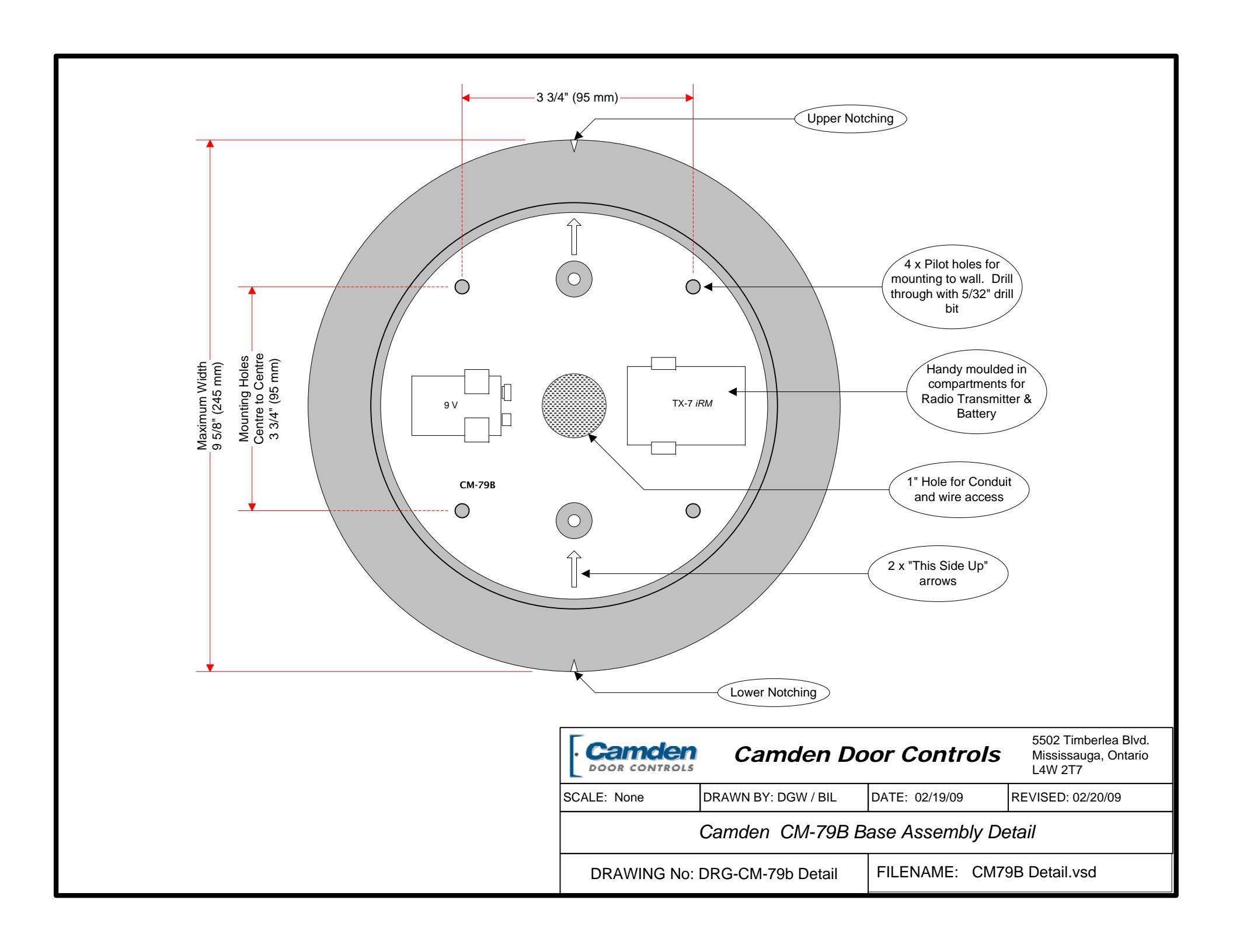
- 1. Locate the 4 pilot holes in the base assembly (CM-79B). They are not drilled all the way through so that you may drill your own holes to match existing layout or, site conditions. Drill 4 x 5/32" (minimum) holes through base. 2. Mark an "X" on the wall at the desired mounting height. Using a level, draw a vertical pencil line at least 5" above and below your "X".
- 3. Hold the base assembly on the wall with the "X" visible though the centre hole, and the arrows pointing up. Line up the top & bottom leveling notches with the vertical pencil line. Mark the drilling locations with a pencil or centerpunch.
- 4. Remove the base assembly and drill holes in wall. Insert the appropriate wall fasteners.
- 5. If you wish to use the supplied weather gasket, remove the backing paper, and attach to rear of CM-79B. If hardwiring the CM-79 you will notice a perforated slot opening in the centre of the gasket to accommodate wiring. Alternatively, a channel in the perimeter allows a bead of caulking for mounting to rough surfaces.
- 6. Fasten the base assembly to the wall with supplied screws.
- 7. If using Radio controls, we have molded-in compartments to hold the transmitter and battery securely. Install transmitter, battery and pull switch wiring out full length.
- 8. Line up part A over part B, and partially screw in the two
- #6-32 Allen-head screws included in kit. (Do not use the short screws provided with your switch.)
- 9. Place your 6" switch over the two screws, install wiring connectors to switch, and centre in the opening.
- 10. Tighten the screws firmly using the Allen key provided with switch.
Mounting to a Single-gang in-wall box (Configuration #2)
- 1. If you wish to use the supplied weather gasket, punch out the centre perforated section first. Remove the backing paper, ensure the two W' holes line up, and affix to the back of CM-79A. Alternatively, a channel in the perimeter allows caulking to rough surfaces.
- 2. Place the CM-79A over the electrical box, and screw in the two #6-32 Allen-head screws (included in kit) by a few threads only. (Do not use the short screws provided with switch.)
- 3. Place your 6" switch over the two screws, install wiring connectors to switch, and centre in the opening.
- 4. Tighten the screws firmly using the Allen key provided with switch.
Mounting to 2-Gang or 4 x 4 in-wall boxes (Configurations #3 & 4)
- 1. If you wish to use the supplied weather gasket, punch out the centre perforated section first. Remove the backing paper, ensure the two W' holes line up, and affix to the back of CM-79A. Alternatively, a channel in the perimeter allows caulking to rough surfaces.
- 2a. Double-gang Electrical box. Using the screws provided in Parts Bag 'C', screw the CM-49C adapter plate to electrical box. (Screws provided with switch are too short).
- 2b. '4 x 4' Electrical box. Using the two #8-32 screws provided with electrical box, fasten CM-49C Adapter plate securely.
- 3. Place CM-79A over adapter plate, and screw the two supplied #6-32 Allen-head screws in by a few threads only.
- 4. Place your 6" switch over the two screws, install wiring connectors to switch, and centre in the opening.
- 5. Tighten the screws firmly using the Allen key provided with switch.
CM-79 Installation Instructions.doc Revision: 19/02/2009 3:55 PM Part No.: 40-82B096
Parts Included in complete Kit:
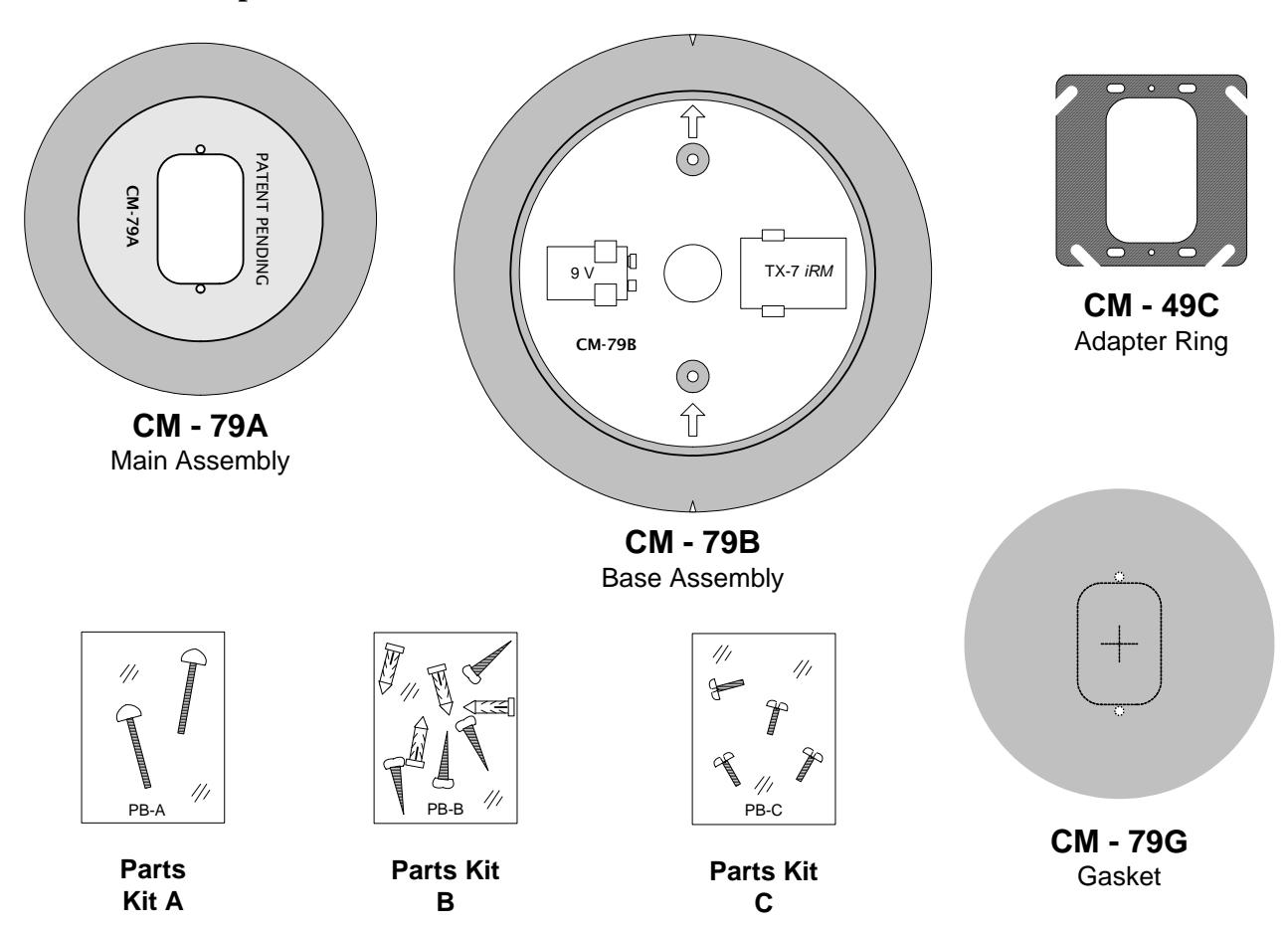
The CM-79 may be ordered as a complete kit, or individual components
Mounting Configurations
The CM-79 complete kit allows a 6" round all active switch (CM-60 series) to be installed in any in-wall electrical box, or surface mounted. The chart below provides the mounting configurations and components required. Refer to the diagram above for parts.
|
MOUNTING
STYLE |
MAIN
CM-49A |
BASE
CM-79B |
ADAPTER
CM-49C |
GASKET
CM-49G |
PARTS
KITS |
||
|---|---|---|---|---|---|---|---|
| A | В | C | |||||
| Surface mount to a solid/hollow wall (no electrical box) | 1 | 1 | Not Required | Optional | | √ | 1 | |
| Mount to a single-gang in-wall electrical box | √ | Not Required | Not Required | Optional | | √ | ||
| Mount to a double-gang in-wall electrical box | √ | Not Required | 1 | Optional | √ | √ | |
| Mount to a 4 x 4 in-wall electrical box | 1 | Not Required | 1 | Optional | 1 | 1 | 1 |
| Mount to Glass | Not recommended due to safety issues | ||||||
| Mount to Surface Box | Not recommended due to incompatibility | ||||||
| Mount to a "wallgrabber" | Not recommended due to insufficient strength | ||||||