Camden Lazerpoint RF RX-92 Full-Function Receiver Installation Instructions
Open the original PDF document
View PDF


Lazerpoint™ RF RX-92 Full-Function Receiver
Installation Instructions
Section 1
General Description
Camden Lazerpoint™ Radio Controls comprise the following models:
CM-TX-9 Wall switch ready transmitter
CM-RX-91 Basic Receiver
CM-RX-92 Full function (dual relay) Receiver.
This instruction manual covers the TX-9 and RX-92 models as well as the plug-in daughterboard's, and related accessories.
Camden Lazerpoint™ RF is the first system designed to address the specific needs of the Automatic Door industry. Unlike typical "garage door" RF, Camden's Lazerpoint™ operates at 915 MHz frequency to "cut through" the noise and clutter, and penetrate typical building materials to ensure a reliable installation every time.
TX-9 transmitters utilize readily available AAA batteries, and special circuitry assures long life. A proprietary piezo sounder is used to annunciate low battery, battery level, and "stuck switch" conditions.
Two receiver models are offered – the basic single relay RX-91, and the full function RX-92. The RX-92 offers 6 operating modes including dual independent channels, latching, and bi-directional sequencing.
Both receivers can be fitted with plug-in daughterboard's ensuring compatibility with older RF technologies. Up to two such boards may be installed at one time, simultaneously allowing the receiver to work with three different frequencies – another Camden exclusive.
Both receiver models feature convenient terminal strip connections, visual signal strength indicators, and 40 code memory with push-and-learn technology.
Section 2
Installation
Mounting
The TX-9 is designed to mount behind a switch in a wallbox, post, or other suitable enclosure. Double sided tape is used to attach the circuit board and battery holder securely to the enclosure. Even though the circuit board is conformal coated, care should be taken to ensure the transmitter does not get wet.
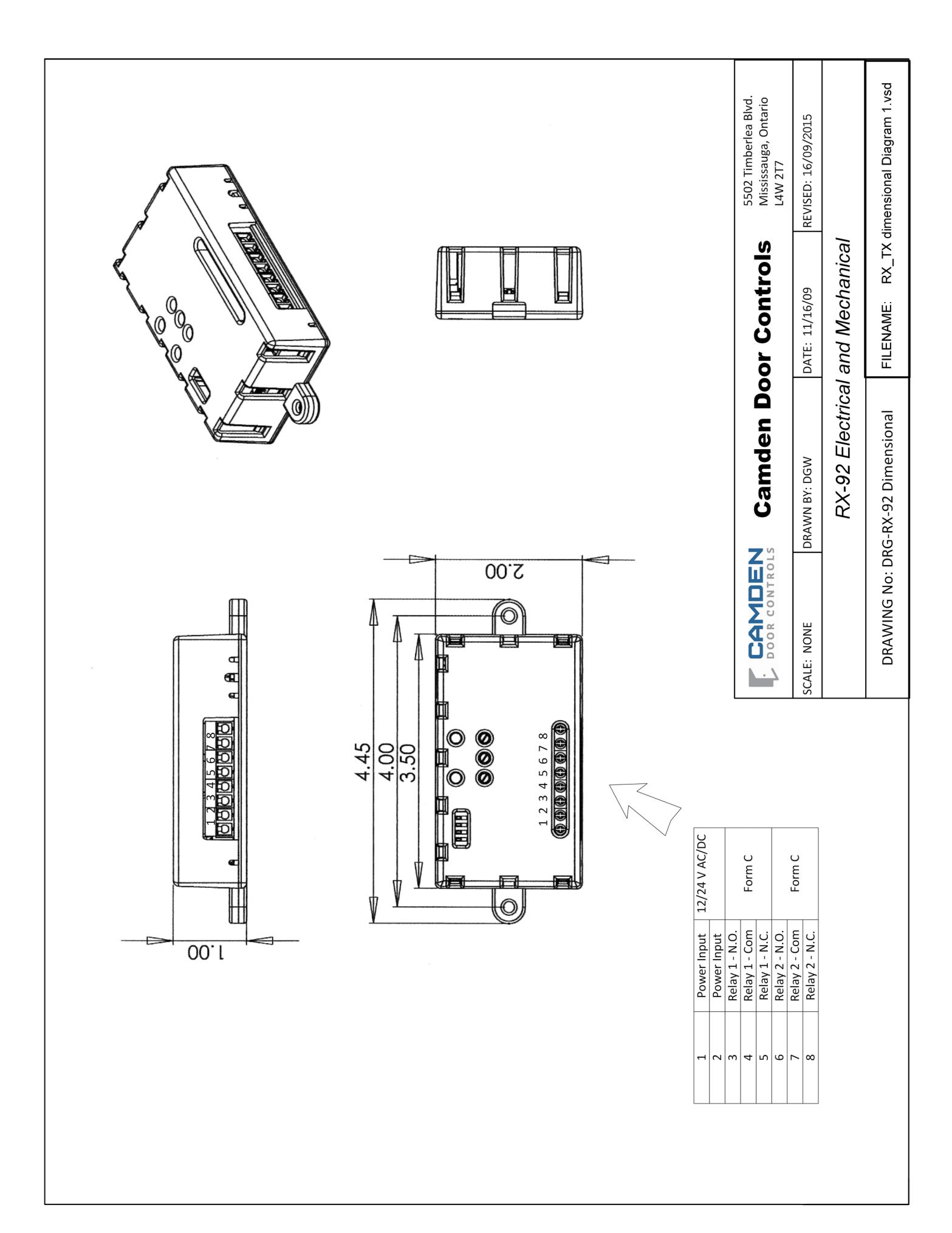
The RX-92 receiver is designed to mount inside the automatic door header. Screw holes are located at each end of the receiver case, or the included velcro may also be used to hold it securely.
For Dimensional information refer to RX-92 Electrical and Mechanical Drawing on Page 5.
Wiring
Wiring of this unit is dependant on the application and mode. Determine the appropriate mode, and then proceed to the section and drawing indicated.
Note: Do not use the Lazerpoint RF system as a Safety device!!. If safety devices are used, always wire them directly to the operator control box.
Section 3
Set-up Instructions
The RX-92 has two relays, and three potentiometers with two 1 – 30 second adjustable Hold time (or delay-on-release) and a 1 – 15 second delay-on-activate for the second relay. The 4-position dip switch selects from one of 6 different operating modes.
Dip switch #4 controls the display of LED 1 & LED 2. When set to OFF, it will display the operation of the associated relay(s). When set to ON, it will blink a count to indicate the received signal strength. To facilitate set-up, set to OFF.
Lazerpoint™ RF RX-92 Full-Function Receiver Installation Instructions
Step 1 Select Operating Mode
Select the desired operating mode by setting the first 3 dip switches as follows:
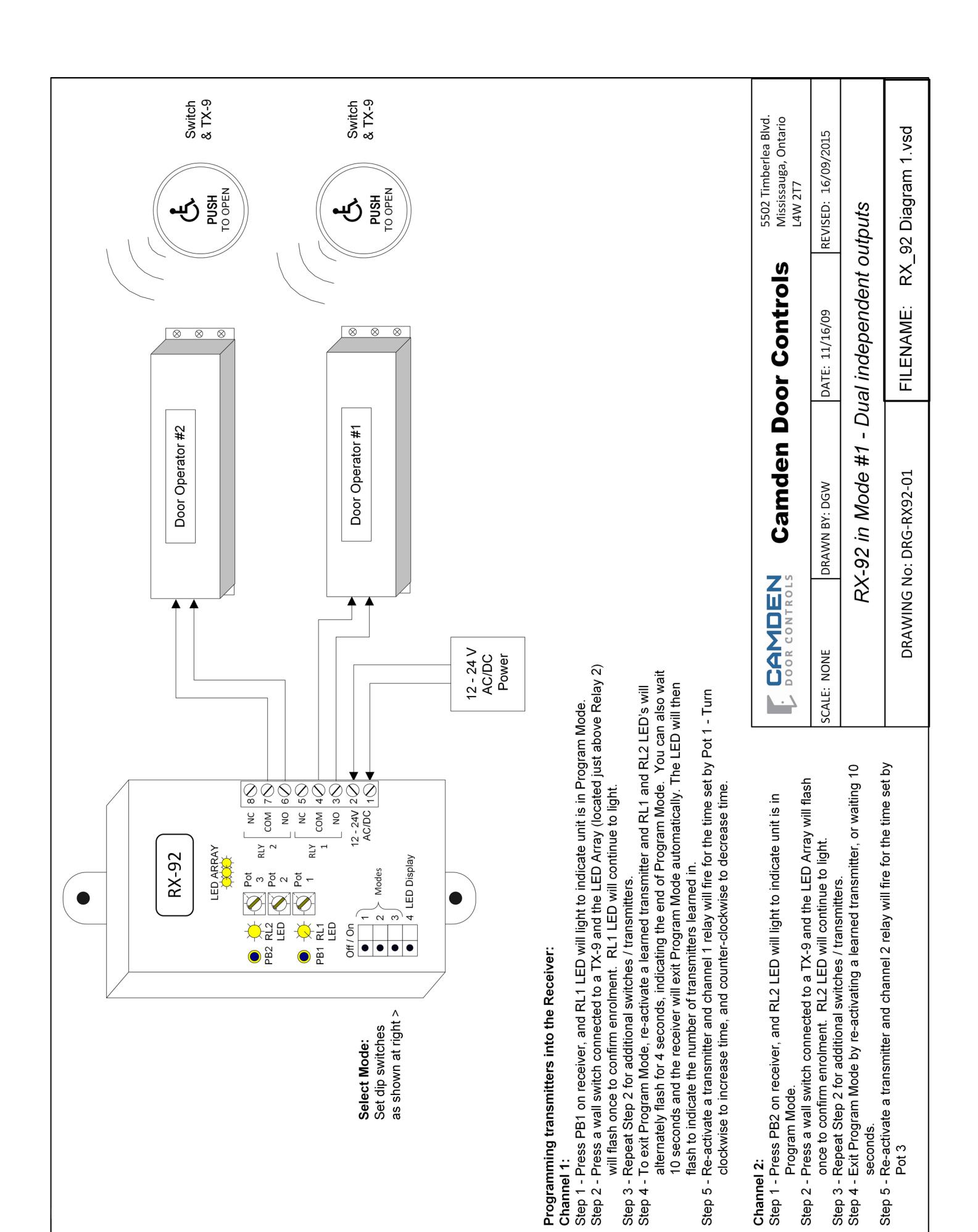
Mode 1 Dual independent outputs
Operates as a two channel receiver. Refer to Diagram 1, Page 6
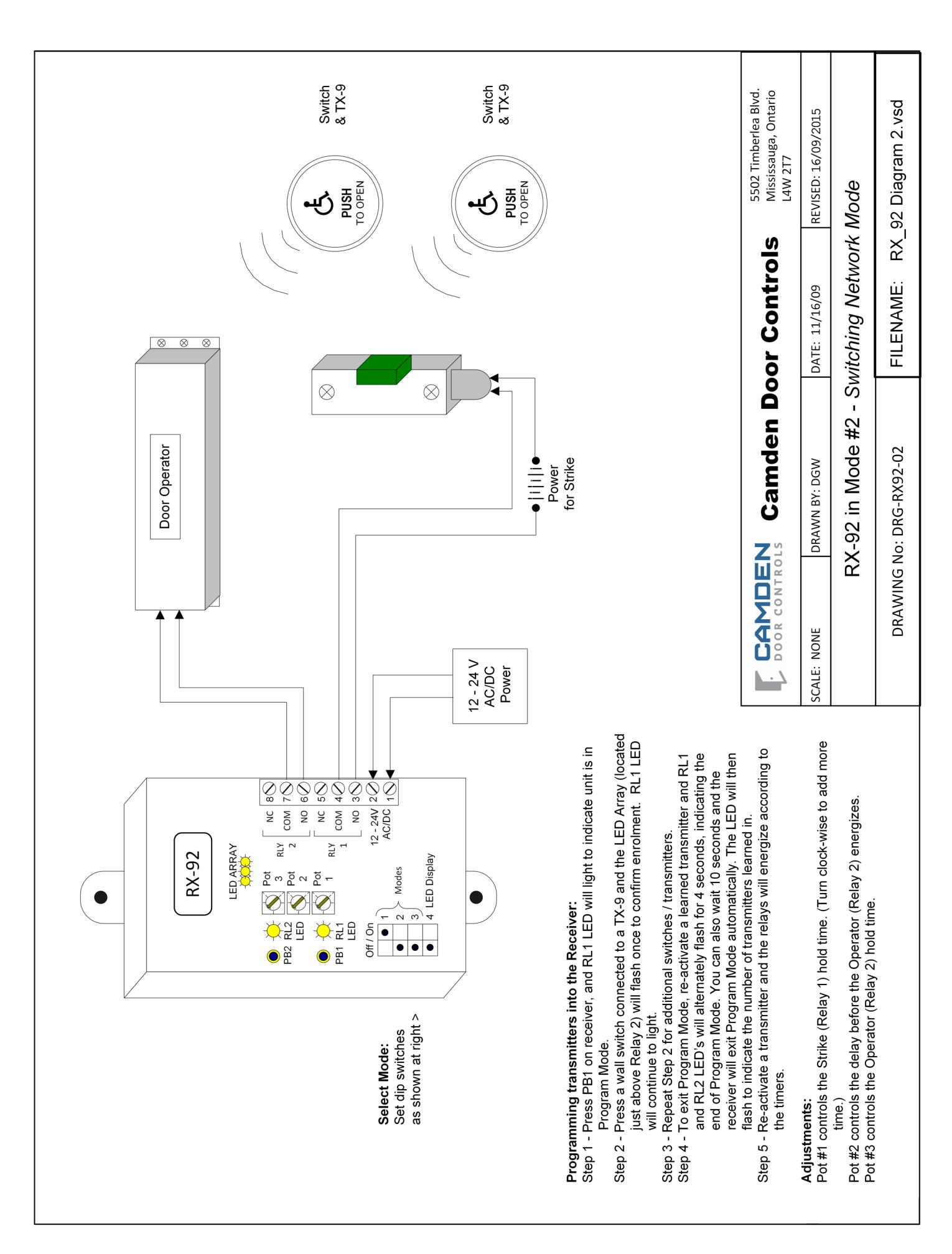
Mode 2 Switching Network
Also known as a switching network or make/ break relay, use this mode with a door operator & lock Refer to Diagram 2, Page 7
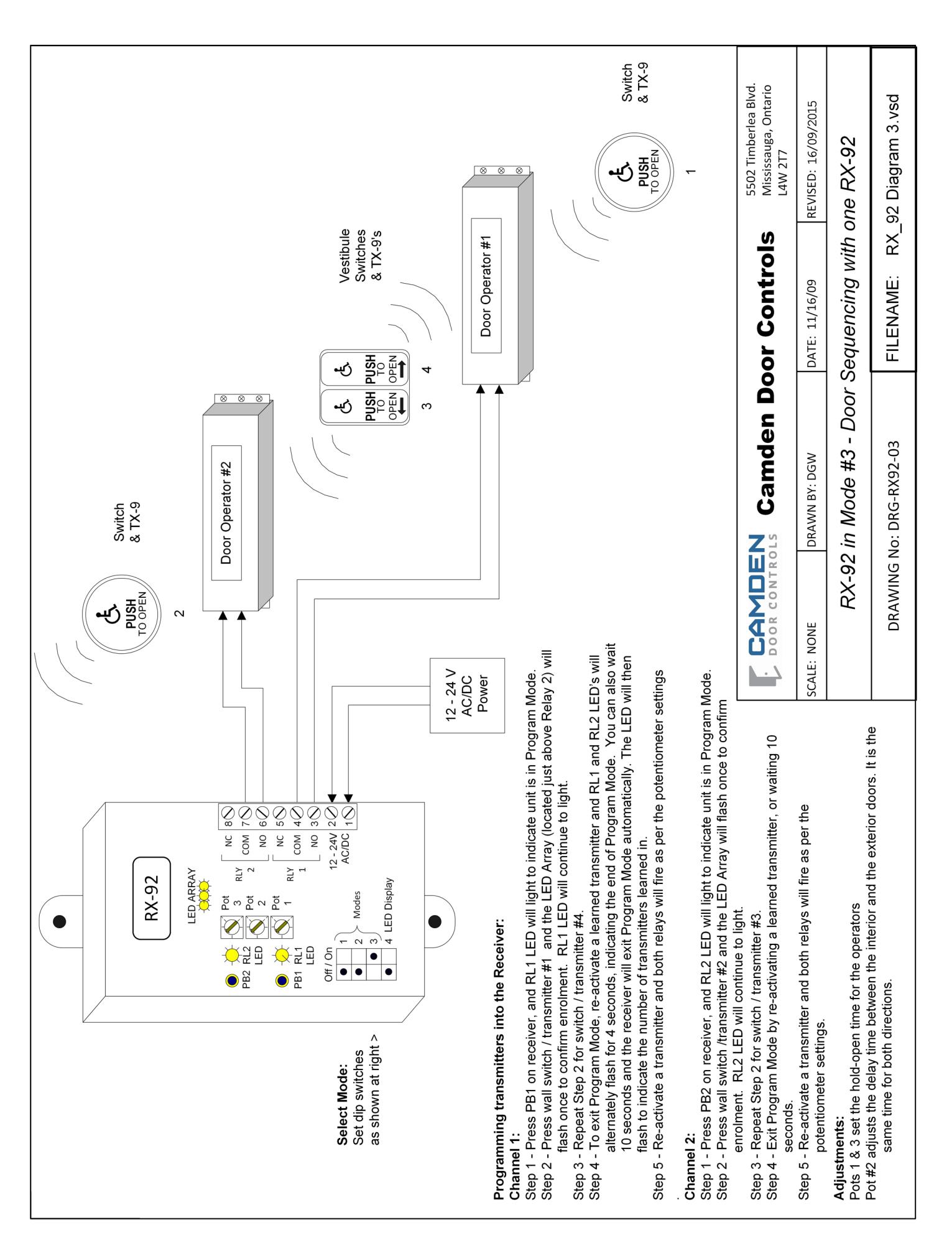
Mode 3 Vestibule Sequencing
Select if you want to sequence two doors in both directions, using just one RX-92 receiver (requires two conductors to the second door) Refer to Diagram 3, Page 8
Mode 4 Vestibule Sequencing
Select if you want to sequence two doors in both directions, using two RX-92's and no wiring between operators
Refer to Diagram 4, Page 9
Mode 5 Latched Mode A
Access Control application. A transmitter signal learned into channel 1 will latch Relay 1. While relay 1 is latched, a transmitter learned into channel 2 will activate relay 2. When channel 1 is in the off state, the RX-92 will ignore channel 2 inputs. Refer to Diagram 5, Page 10
Mode 6 Latched Mode B
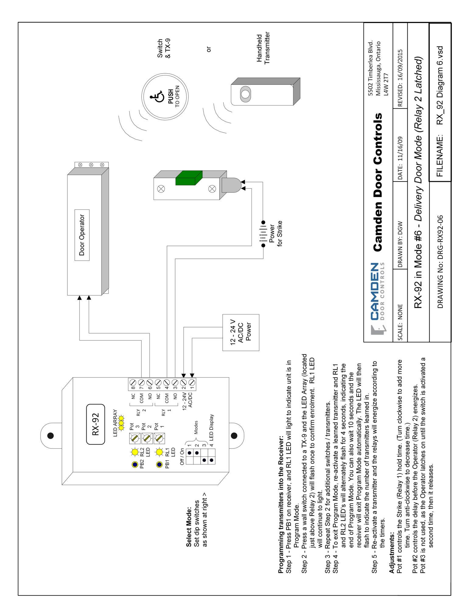
Freight Door application. In this mode a transmitter will active relay 1 for an adjustable time, then latch relay 2. Relay 2 stays latched until another transmitter signal is received then drops out immediately. Refer to Diagram 6, Page 11
Step 2 Connections
Refer to the TX-9 Installation Drawing (supplied with Transmitter) for the following connections.
Connect the transmitter wires to the activating switch (N.O. momentary dry contacts). Insert 2 fresh AAA alkaline batteries (provided) into the battery holder. Press the switch and observe the red LED to ensure proper transmission.
Test the transmitter by pressing and holding the switch for 5 seconds. The piezo speaker should sound 5 beeps, meaning the batteries are at full capacity. This is the Battery Gauge™ feature.
If the piezo beeps only 1 - 3 times, you should change the batteries for fresh (new) ones.
Now press and hold the switch for 15 seconds. The piezo
should now make a distinctive hi-low sound. This signal will sound for 6 seconds, then turn off for a minute, then sound again. This is the "stuck switch indicator" feature. Repeat for additional transmitters.
Wire the receiver according to the specific application drawing. Generally however, wiring is as follows:
Wire the first device (electric lock / operator) to Relay 1 output - terminal 3 is N.O. 4 is Common, and 5 is N.C.
Wire the second device (electric lock or operator) to Relay 2 output - Terminal 6 is N.O., 7 is Common, and 8 is N.C.
Connect 12 or 24 Volt AC or DC to terminals 1 & 2 on the receiver. (The terminals are not polarity sensitive).
Step 3 Learning the Transmitter(s) to the Receiver
The procedure for learning of transmitters is dependant on the specific operating mode. Please refer to the applicable wiring diagram for exact instructions.
General instructions are as follows:
To learn the transmitter into the receiver, press the PB1 (or PB2) button using a small blunt object such as a small blade screwdriver or similar. Within 10 seconds, press the switch connected to a TX-9 transmitter. You should then see the Green LED display light on the receiver to indicate the TX-9 has been received and learned. Repeat with any additional transmitters. Pressing the learned transmitter again will signal the receiver that you are finished programming and LED's 1 & 2 will flash, in an alternating sequence. Pressing the transmitter a third time will activate the relay and corresponding LED, and also the device connected to the relay contacts.
If you wait longer than the 10 second period, the receiver will time out of Learn Mode and revert back to standby. The LED will then flash to indicate the number of transmitters learned into the receiver.
Step 4 Adjustments
The RX-92 has two relay hold timers (delay-on-release) of 1 – 30 seconds each (Pots 1 & 3). There is also a delay-onoperate time for relay two (Pot #2)
To increase time, turn the pot clockwise, or for minimum time, turn the pot counter-clockwise.
Always walk-test the installation and adjust the timers to suit.
Lazerpoint™ RF RX-92 Full-Function Receiver Installation Instructions
Step 5 Testing Signal Strength
By setting Dip Switch #4 to ON, you can display the signal strength of the transmission from a TX-9 transmitter. The benefit is the installer will be able to determine that the transmitter or receiver is in the best possible location and that the transmission is not being hindered by possible interference.
To display signal strength, set Dip switch #4 ON.
Activate the transmitter, and observe the number of flashes of LED 1. One or two RED flashes indicates poor reception, and it is suggested to move the transmitter or receiver until 3 to 5 GREEN flashes are observed. Sometimes moving the transmitter only a few inches one way or another will make a significant difference. Four or five flashes are ideal.
Step 6 Deleting Transmitters
Pressing and holding either PB1 or PB2 for 8 seconds will delete all transmitters. The LED Array will flash rapidly for 4 seconds to indicate erasure of the codes. Note that individual removal of specific codes is not possible at this time.
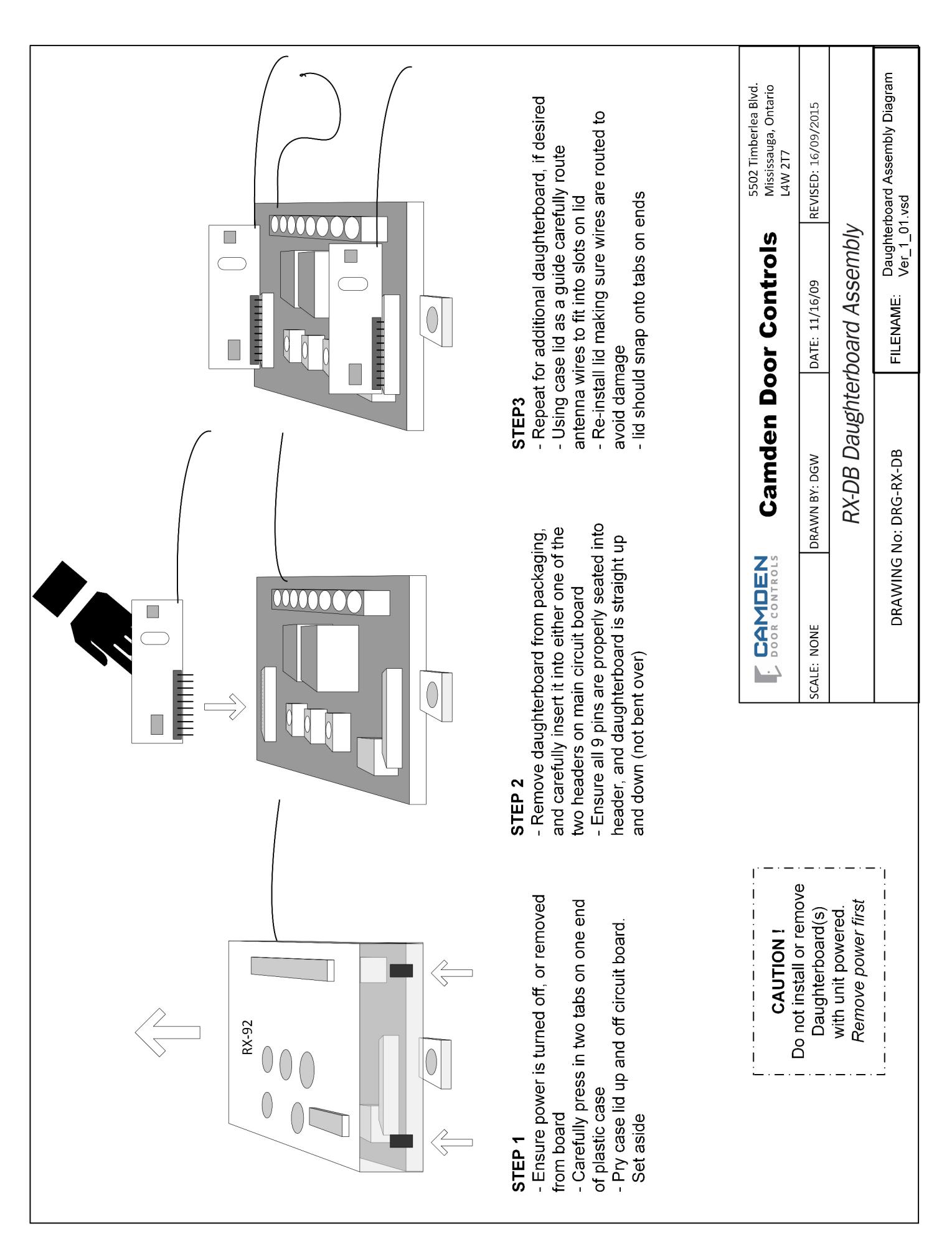
Step 7 Adding Daughterboard's
A unique feature of Camden's Lazerpoint RF is the ability to add one or two daughterboard's, extending compatibility to older technologies. This ability to work with additional frequencies also allows the user to utilize hand-held transmitters as well as wall-switch-ready transmitters.
The daughterboard's may be factory or field installed. Please see Drawing DRG-RX-DB (page 12) for detailed installation instructions.
! Remember to take reasonable care to avoid static electricity whenever handling circuit boards. !
The daughterboards may be identified by the model number and antenna colour, as shown in the chart below:
| Model # | Frequency | Antenna |
|---|---|---|
| RX-DBB | 300 MHz | Blue |
| RX-DBO | 318 MHz | Orange |
| RX-DBR | 390 MHz | Red |
| RX-DBW | 433 MHz | White |
Once installed, the learning of transmitters on above frequencies is identical to the TX-9 transmitter. Also, the 40 code memory limit includes all transmitters, even those learned in on the daughterboards.
Step 8 Using CM-RFCT Cable tool
Since the LED's may be difficult to see once the RX-92 is installed, a 33" long plug-in cable tool is available.
The CM-RFCT Cable Tool plugs into the opening on the side of the receiver, and allows the installer to view LED's mounted on the free end. Pairs of LED's mounted on both sides of the cable increase visibility.
Display status is dependant on Dip switch 4 setting. Turn OFF to view relay status, and turn ON to view the Signal Strength.
When installation is complete, simply unplug the cable tool, coil and save for another job.
Section 4
Technical Data
| Frequency: |
Operates in the 902 – 928 MHz
ISM Band |
|---|---|
| Codes | 1 million unique (20 bit) codes |
| Size | 2 ¼" L x 5/8" W x 3/8" H |
|
Mounting
Switch Connection |
Double sided foam tape
2 x 10" leads with ¼" quick disconnect terminations |
| Built-in Piezo sounder |
Used for Low Battery status,
Battery Gauge™, and Stuck |
Model TX-9 Transmitter
Power 2 x AAA alkaline batteries Battery life Minimum 500,000 operations
Switch indicator.
Range Over 500 ft (open area)
Temperature rating -40 to 185 F (-40 to +85 C)
Model RX-92 Receiver
| Size | 3 ½" L x 2" W x 1" H |
|---|---|
| Mounting |
2 # 8 screws at 4" centers,
or Velcro (supplied) |
| Enclosure | Clear plastic case |
| Operating voltage | 12 / 24 Volts, AC / DC |
| Current Draw | 23 mA nominal @ 24 VAC |
63 mA maximum @ 24 VAC + 5 mA per RF module
Response time 30 – 200 ms Operating Modes Via 4 dip-switches Memory 40 transmitters LED's Indicate: relay status; signal strength; learn mode; erase mode & potentiometer
position Outputs RX-92 – 2 x SPDT relays
Relay contact rating 3 amps @ 30 VDC Time Delays 3 potentiometers:
Relay1 D.O.R. = 1 – 30 sec Relay 2 D.O.O = 1 – 15 sec Relay 2 D.O.R. = 1 – 30 sec
Electrical Life 1 x 10⁵ minimum
Temperature rating -40 to 185 F (-40 to +85 C)
Certifications ·FCC Part 15 Compliant ·Canada RSS/CNR210:1078 1032 061A
·Meets: IEC60601-1-2:2007
Patent Pending
Accessories:
Plug-in daughterboard's extend capability with other frequencies. Refer to the following chart:
|
Daughterboard
Model # |
Operational
Frequency |
Antenna
Colour |
|---|---|---|
| RX-DBB | 300 MHz | Blue |
| RX-DBO | 318 MHz | Orange |
| RX-DBR | 390 MHz | Red |
| RX-DBW | 433 MHz | White |
CM-RFCT: A 33" long cable-tool for high visibility of relay status and signal strength
Section 5
Warranty
Camden Door Controls guarantees the Lazerpoint RF (TX-9, RX-91,or RX-92 models) to be free from manufacturing defects for 3 years from date of sale. If during the first 3 years a Lazerpoint RF component fails to perform correctly, it may be returned to our factory where it will be repaired or replaced (at our discretion) without charge. Except as stated herein, Camden extends no warranties expressed or implied regarding function, performance or service.
NOTE: Batteries are exempt from this warranty!
Questions? Call us toll-free at 1-877-226-3369
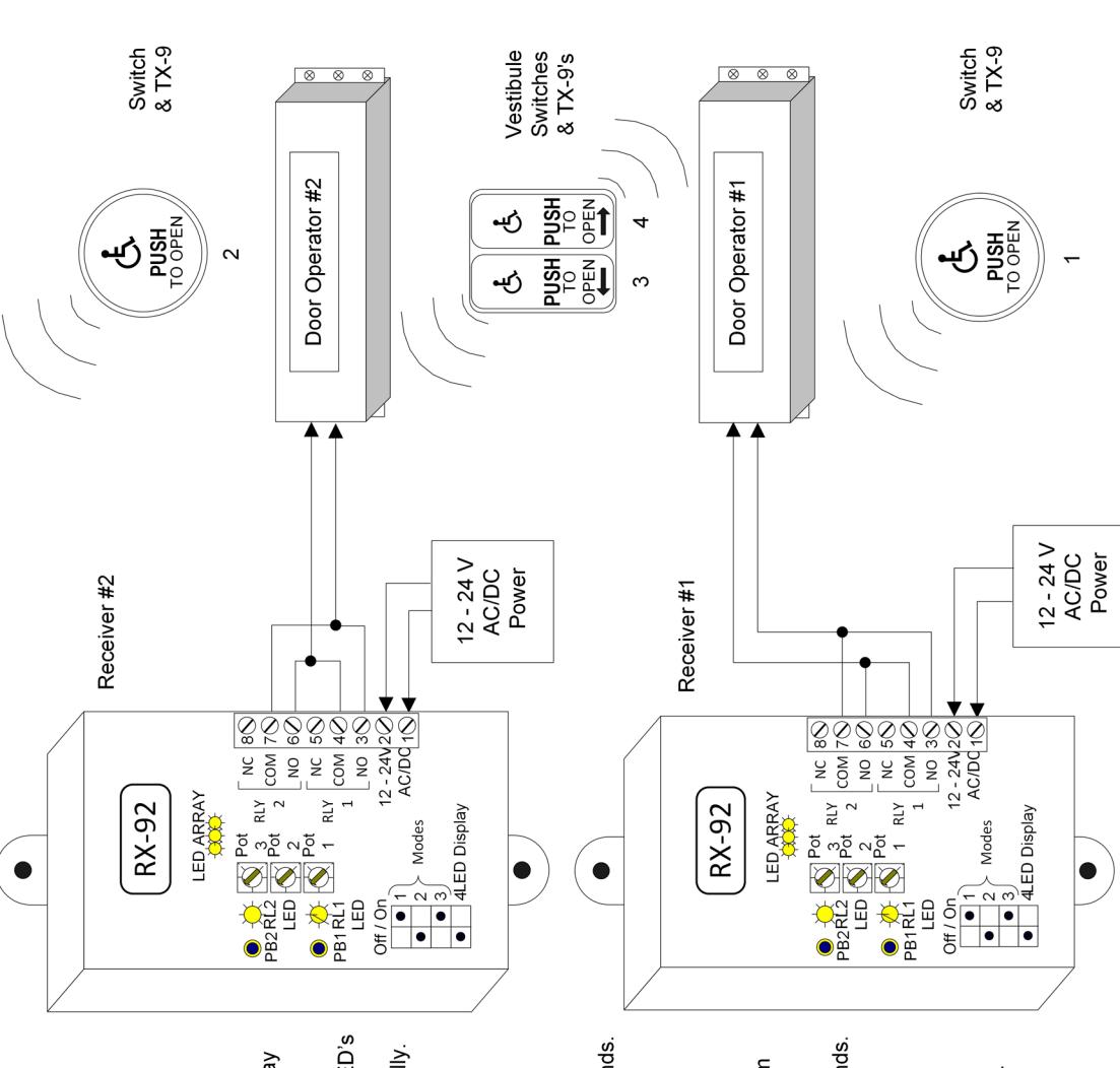
Select Mode: Set dip switches as shown at right. (same on both receivers)
Programming transmitters into the Receivers:
Receiver #1
Channel 1:
-
Step 2 Press wall switch / transmitter #1 and the LED Array (located just above Relay Step 1 - Press PB1 on receiver #1, and RL1 LED will light to indicate Program Mode.
-
2) will flash once to confirm enrolment. RL1 LED will continue to light.
-
2) will flash once to confirm enrolment. RL1 LED will continue to light.
-
Step 3 Repeat Step 2 for switch / transmitter #4. Step 4 To exit Program Mode, re-activate a learned transmitter and RL1 and RL2 LED's can also wait 10 seconds and the receiver will exit Program Mode automatically will alternately flash for 4 seconds, indicating the end of Program Mode. You
- The LED will then flash to indicate the number of transmitters learned in. Step 5 - Re-activate transmitter 1 or 4, and relay #1 will fire.
Channel 2:
- Step 1 Press PB2 on receiver, and RL2 LED will light to indicate unit is in Program Mode.
- Step 2 Press wall switch /transmitter #2 and the LED Array will flash once to confirm enrolment. RL2 LED will continue to light
-
Step 3 Exit Program Mode by re-activating a learned transmitter, or waiting 10 seconds. Step 4 Re-activate transmitter #2 and relay #2 will fire.
Receiver #2
Channel 1:
- Step 1 Press PB1 on receiver #2, and RL1 LED will light to indicate Program Mode.
- Step 2 Press wall switch / transmitter #2 and the LED Array will flash once to confirm enrolment. RL1 LED will continue to light.
-
Step 3 Repeat Step 2 for switch / transmitter #3. Step 4 Exit Program Mode by re-activating a learned transmitter, or waiting 10 seconds.
- Step 5 Re-activate transmitter 2 or 3 and relay #1 will fire.
Channel 2:
-
Step 2 Press wall switch /transmitter #1 and the LED Array will flash once to confirm Step 1 - Press PB2 on receiver, and RL2 LED will light to indicate Program Mode.
- enrolment. RL2 LED will continue to light.
-
Step 3 Exit Program Mode by re-activating a learned transmitter, or wait 10 seconds. Step 4 Re-activate transmitter #1, and relay #2 will fire.
Adjustments:
Pot #1 controls the operator hold time for the nearest transmitter. (Turn clockwise to add more time. Turn anti-clockwise to decrease time)
Pot #2 controls the delay before relay #2 fires, therefore the delay between the two doors. Each receiver can be set independently.
Pot #3 controls the operator hold time for the furthest transmitter.

Camden Door Controls
DATE: 11/16/09
DRAWN BY: DGW
SCALE: NONE
Mississauga, Ontario L4W 2T7
REVISED: 16/09/2015
5502 Timberlea Blvd.
RX-92 in Mode #4 - Door Sequencing with two RX-92's
DRAWING No: DRG-RX92-04
92 Diagram 4.vsd FILENAME:
above Relay 2) will flash once to confirm enrolment. RL1 LED will continue to light
alternately flash for 4 seconds, indicating the end of Program Mode. You can also wait 10 Step 3 - Repeat Step 2 for any additional transmitters. Step 4 - To exit Program Mode, re-activate the learned transmitter and RL1 and RL2 LED's will
seconds and the receiver will exit Program Mode automatically. The LED will then flash to indicate the number of transmitters learned in.
Step 5 - Re-activate the same transmitter and relay 1 will energize and remain energized until the input is activated again, then it will release.
Channel 2:
Step 1 - Press PB2 on receiver, and RL2 LED will light to indicate unit is in Program Mode.
Step 2 - Press a wall switch connected to a TX-9 and the LED Array (located just above Relay 2) will
flash once to confirm enrolment. RL2 LED will continue to light.
Step 3 - Repeat Step 2 for any additional transmitters.
Step 4 - Exit Program Mode by re-activating a learned transmitter or waiting 10 seconds
period set by pot #3, but only if Relay/Channel 1 is activated. If it is not, Re-activate the same transmitter and relay 2 will energize for the time then Relay/Channel 2 will not activate, and will be ignored Step 5 -
Adjustments: Pot #3 controls the Operator (Relay 2) hold time. (Turn clockwise to add more time. Turn anti-clockwise to decrease time.)
| Door Cont | |
|---|---|
| Camden Do | |
|
CAMDEN
DOOR CONTROLS |
5502 Timberlea Blvd. Mississauga, Ontario
<u>s</u>|0
REVISED: 16/09/2015 L4W 2T7
DATE: 11/16/09
DRAWN BY: DGW
SCALE: NONE
| _ | |
|---|---|
| tched | |
| 1 Lat | |
| Relay | |
| 7 | |
| Mode ( | |
| ontrol | |
| s C | |
| Access C | |
| 7 - 5 | |
| le #5 | |
| Моо | |
| L | |
| X-92 in | |
| ı |
FILENAME: DRAWING No: DRG-RX92-05
92 Diagram 5.vsd
Lazerpoint™ RF RX-92 Full-Function Receiver Installation Instructions
IC & FCC INFORMATION FOR USERS
IC: 8725A-RX9192
This device complies with Industry Canada's licence-exempt RSSs. Operation is subject to the following two conditions:
- (1) This device may not cause interference; and
- (2) This device must accept any interference, including interference that may cause undesired operation of the device.
Le présent appareil est conforme aux CNR d'Industrie Canada applicables aux appareils radio exempts de licence. L'exploitation est autorisée aux deux conditions suivantes :
- 1) l'appareil ne doit pas produire de brouillage;
- 2) l'utilisateur de l'appareil doit accepter tout brouillage radioélectrique subi, même si le brouillage est susceptible d'en compromettre le fonctionnement.
This radio transmitter (8725A- RX9192) has been approved by Industry Canada to operate with the antenna types listed below with the maximum permissible gain indicated. Antenna types not included in this list, having a gain greater than the maximum gain indicated for that type, are strictly prohibited for use with this device.
Le présent émetteur radio (8725A- RX9192) a été approuvé par Industrie Canada pour fonctionner avec les types d'antenne énumérés ci dessous et ayant un gain admissible maximal. Les types d'antenne non inclus dans cette liste, et dont le gain est supérieur au gain maximal indiqué, sont strictement interdits pour l'exploitation de l'émetteur.
Antenna Specification
Model: Camden Lazerpoint Proprietary PCB Antenna
Center Frequency: 915MHz
Recom.. Freq. Range: 903-928MHz
Wavelength: ¼ Wave Peak Gain: 0dBi Impedance: 50-ohms Connector: 2-pin Header
Oper. Temp. Range: -40° to +85°C
FCC ID: 2AHAB-RX9192
This device complies with part 15 of the FCC Rules. Operation is subject to the following two conditions: (1) This device may not cause harmful interference, and (2) this device must accept any interference received, including interference that may cause undesired operation.
This equipment has been tested and found to comply with the limits for a Class B digital device, pursuant to part 15 of the FCC Rules. These limits are designed to provide reasonable protection against harmful interference in a residential installation. This equipment generates, uses and can radiate radio frequency energy and, if not installed and used in accordance with the instructions, may cause harmful interference to radio communications. However, there is no guarantee that interference will not occur in a particular installation. If this equipment does cause harmful interference to radio or television reception, which can be determined by turning the equipment off and on, the user is encouraged to try to correct the interference by one or more of the following measures:
- —Reorient or relocate the receiving antenna.
- —Increase the separation between the equipment and receiver.
- —Connect the equipment into an outlet on a circuit different from that to which the receiver is connected.
- —Consult the dealer or an experienced radio/TV technician for help.
Changes or modifications made to this equipment not expressly approved by Camden Door Control could void the user's authority to operate the equipment.
Push Buttons Key Pads Strikes Magnetic Locks Key Switches Relays & Timers Access Control


5502 Timberlea Blvd., Mississauga, ON Canada L4W 2T7
www.camdencontrols.com Toll Free: 1.877.226.3369

File: Lazerpoint RF RX_92 Instructions.doc -Rev. 3 Revision: 19/05/2016 Part No.: 40-82B122