Camden Lazerpoint RF RX-90 Advanced Single Relay Receiver Installation Instructions
Open the original PDF document
View PDF


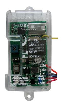
LazerpointTM RF RX-90 Advanced Single Relay Receiver
Installation Instructions
Section 1
General Description
Camden Lazerpoint™ Radio Controls comprise the following models:
- CM-TX-9 Wall switch ready transmitter
- CM-TX-99 Plug-in transmitter
- CM-TXLF 1, 2 & 4 button fob transmitters
- CM-RX-90 Advanced single relay receiver
- CM-RX-91 Basic single relay receiver
- CM-RX-92 Full function (dual relay) receiver.
Camden Lazerpoint™ RF is the first system designed to address the specific needs of the Automatic Door industry. Unlike typical "garage door" RF, Camden's Lazerpoint™ operates at 915 MHz frequency to "cut through" the noise and clutter, and penetrate typical building materials to ensure a reliable installation every time.
Three receiver models are offered – the basic single relay RX-91, the full function RX-92 and the advanced single relay RX-90. The RX-90 offers 3 operating modes including delayed, no delay and latched.
Camden CM-RX-90 features a convenient wiring harness, 18" in length, visual relay status, and 40 code memory with push-and-learn technology.
Section 2
Features
-
3 Modes of Operation:
- Delayed (1 15 Seconds)
- No Delay (1 30 Seconds)
- Latching
- 40 Transmitter capacity, either delayed, non-delayed or both
- Form 'C' Relay Output
- 12/24V AC/DC operation
- 915 MHz Lazerpoint Technology
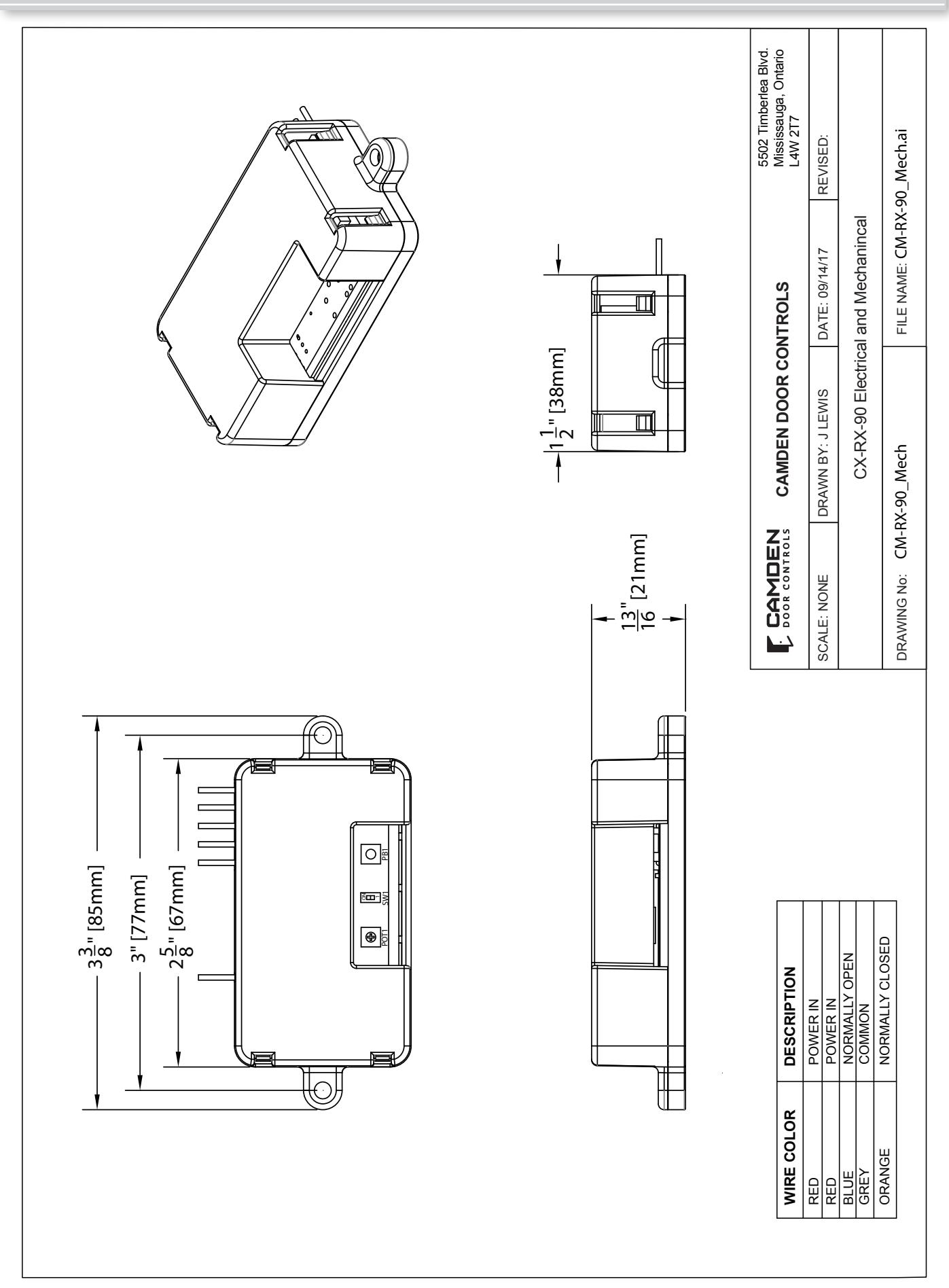
- Small Size: 2 5/8"H x 1 1/2"W x 13/16"D (67mm x 38mm x 21mm)
Section 3
Installation
Mounting
The RX-90 receiver is designed to mount inside the automatic door header. Screw holes are located at each end of the receiver case, or the included velcro may also be used to hold it securely.
For dimensional information refer to RX-90 electrical and mechanical Drawing on Page 4.
Wiring
Note: Do not use the Lazerpoint RF system as a Safety device!!. If safety devices are used, always wire them directly to the operator control box.
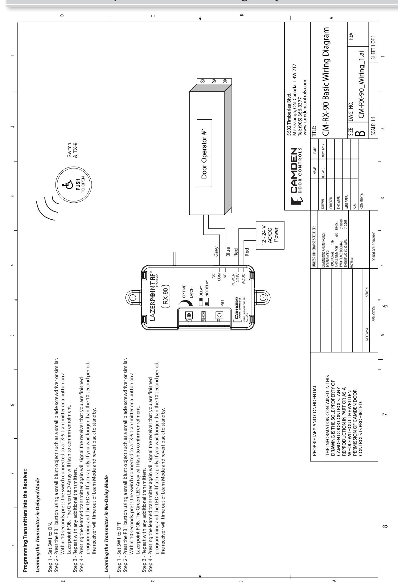
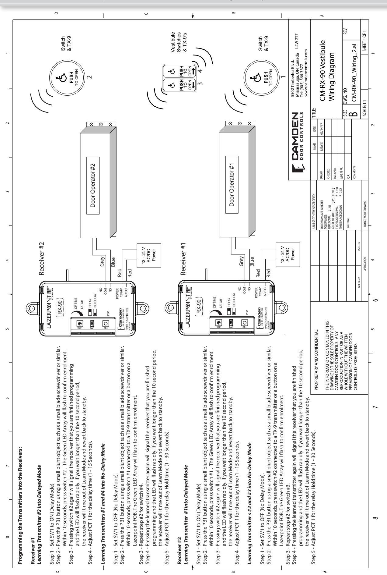
Refer to the RX-90 Wiring Diagram on Page 5, and wire the receiver as follows:
Wire the device (electric lock / operator) to the Relay output terminal 3 is N.O. 4 is Common, and 5 is N.C.
Connect 12 or 24 Volt AC or DC to terminals 1 & 2 on the receiver. (The terminals are not polarity sensitive ).
| Wire | Description |
|---|---|
| Red | Power In |
| Red | Power In |
| Blue | Normally Open |
| Grey | Common |
| Orange | Normally Closed |
Section 4
Set-up Instructions
Step 1
Learning the Transmitter(s) to the Receiver
A receiver can have up to 40 transmitters paired with it. The transmitter can be paired as delayed, non-delayed or a combination of both, making RX-90 ideal for bi-directional door sequencing.
Learning the Transmitter in Delayed Mode
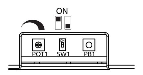
Set SW1 to ON.
Press the PB1 button using a small blunt object such as a small blade screwdriver or similar. Within 10 seconds, press the switch connected to a TX-9 transmitter or a button on a Lazerpoint FOB. The Green LED Array will flash to confirm enrolment. Repeat with any additional transmitters. Pressing the learned transmitter again will signal the receiver that you are finished programming and the LED will flash rapidly. Pressing the transmitter a third time will activate the relay and the LED, and also the device connected to the relay contacts after the delay time set by POT1.
If you wait longer than the 10 second period, the receiver will time out of Learn Mode and revert back to standby.
Learning the Transmitter in No-Delay Mode
Set SW1 to OFF
Press the PB1 button using a small blunt object such as a
small blade screwdriver or similar. Within 10 seconds, press the switch connected to a TX-9 transmitter or a button on a Lazerpoint FOB. The Green LED Array will flash to confirm enrolment. Repeat with any additional transmitters. Pressing the learned transmitter again will signal the receiver that you are finished programming and the LED will flash rapidly. Pressing the transmitter a third time will activate the relay and the LED, and also the device connected to the relay contacts.
If you wait longer than the 10 second period, the receiver will time out of Learn Mode and revert back to standby.
Step 2
Adjustments
The delay before operate and the relay On-Time are controlled by POT1.
Delayed Mode
The RX-90 has a delay before operate timer.
Set SW1 to ON.
Adjust POT1 clockwise to increase the delay timer from 0 to 15 seconds. The LED will light and become brighter as the delay time is increased and become dim as the delay time is decreased. The LED starts to flash once the maximum delay time has been reached. Back off the delay time until the LED is solid again for maximum delay time.
No-Delay Mode
The RX-90 can be adjusted to activate the output relay without a delay. The relay On-Time is adjustable from 1 to 30 seconds.
Set SW1 to OFF.
Adjust POT1 Clockwise/counterclockwise to adjust the relay On-Time (1 to 30 Seconds). To increase the time, turn the pot clockwise, or for minimum time, turn the pot counterclockwise. The LED will light and become brighter as the Relay On-Time is increased. The LED starts to flash once the maximum On-Time has been reached. Back off the POT until the LED is solid again for maximum On-Time.
Latching Mode
The RX-90 has a latching mode. Activating the transmitter will latch the output relay ON. Activating the transmitter a second time will latch the Relay OFF.
SW1 can be set to either ON/OFF.
Adjust POT1 clockwise until the LED starts to flash. The RX-90 is in latching mode at this point. To remove latching mode, turn POT 1 counter clockwise until the LED is solid again.
Note: Latching mode disables delayed mode. Transmitter programmed as delayed mode will work as latching mode transmitter.
Step 3
Deleting Transmitters Delay Mode Transmitters
Set SW1 to ON.
Pressing and holding PB1 for 8 seconds will delete all transmitters delay mode. The LED will flash rapidly for 4 seconds to indicate erasure of the codes.
No Delay Mode Transmitters
Set SW1 to OFF.
Pressing and holding PB1 for 8 seconds will delete all transmitters no delay mode. The LED will flash rapidly for 4 seconds to indicate erasure of the codes.
Note that individual removal of specific codes is not possible at this time.
Section 5
Technical Data
| Model | RX-90 Receiver |
|---|---|
| Size |
2 5/8"H x 1 1/2"W x 13/16"D
(67mm x 38mm x 21mm) |
| Mounting |
2 # 4 screws at 3" centers,
or Velcro (supplied) |
| Enclosure | Clear plastic case |
| Operating Voltage | 12 / 24 Volts, AC / DC |
| Current Draw |
23 mA nominal @ 24 VAC
43 mA maximum @ 24 VAC |
| Response Time | 30 – 200 ms |
| Memory Delay & No Delay | 40 transmitters total |
| LED's |
Indicate: relay status;
learn mode; erase mode & potentiometer position |
| Output | 1 x SPDT Relay contact |
| Rating | 3 amps @ 30 VDC |
| Operating Time | 1 – 30 seconds |
| Electrical Life | 1 x 10⁵ minimum |
|---|---|
| Temperature Rating | -40 to 185°F (-40 to +85°C) |
| Certifications |
- FCC Part 15 Compliant
- Canada RSS CNR210:1078 1032 061A - Meets: IEC60601-1-2:2007 - Patent Pending |
Section 6
Warranty
Camden Door Controls guarantees the Lazerpoint RF to be free from manufacturing defects for 3 years from date of sale. If during the first 3 years a Lazerpoint RF component fails to perform correctly, it may be returned to our factory where it will be repaired or replaced (at our discretion) without charge. Except as stated herein, Camden extends no warranties expressed or implied regarding function, performance or service.
NOTE: Batteries are exempt from this warranty!
IC & FCC INFORMATION FOR USERS
This device complies with Industry Canada's licence-exempt RSSs. Operation is subject to the following two conditions:
- (1) This device may not cause interference; and
- (2) This device must accept any interference, including interference that may cause undesired operation of the device.
Le présent appareil est conforme aux CNR d'Industrie Canada applicables aux appareils radio exempts de licence. L'exploitation est autorisée aux deux conditions suivantes :
- 1) l'appareil ne doit pas produire de brouillage;
- 2) l'utilisateur de l'appareil doit accepter tout brouillage radioélectrique subi, même si le brouillage est susceptible d'en compromettre le fonctionnement.
This radio receiver has been approved by Industry Canada to operate with the antenna types listed below with the maximum permissible gain indicated. Antenna types not included in this list, having a gain greater than the maximum gain indicated for that type, are strictly prohibited for use with this device.
Le présent receveur radio a été approuvé par Industrie Canada pour fonctionner avec les types d'antenne énumérés ci dessous et ayant un gain admissible maximal. Les types d'antenne non inclus dans cette liste, et dont le gain est supérieur au gain maximal indiqué, sont strictement interdits pour l'exploitation de l'émetteur.
Antenna Specification
Model: Camden Lazerpoint Proprietary PCB Antenna
Center Frequency: 915MHz
Recom. Freq. Range: 903-928MHz
Wavelength: ¼ Wave Peak Gain: 0dBi Impedance: 50-ohms Connector: 2-pin Header
Oper. Temp. Range: -40° to +85°C
This device complies with part 15 of the FCC Rules. Operation is subject to the following two conditions: (1) This device may not cause harmful interference, and (2) this device must accept any interference received, including interference that may cause undesired operation.
This equipment has been tested and found to comply with the limits for a Class B digital device, pursuant to part 15 of the FCC Rules. These limits are designed to provide reasonable protection against harmful interference in a residential installation. This equipment generates, uses and can radiate radio frequency energy and, if not installed and used in accordance with the instructions, may cause harmful interference to radio communications. However, there is no guarantee that interference will not occur in a particular installation. If this equipment does cause harmful interference to radio or television reception, which can be determined by turning the equipment off and on, the user is encouraged to try to correct the interference by one or more of the following measures:
- —Reorient or relocate the receiving antenna.
- —Increase the separation between the equipment and receiver.
- —Connect the equipment into an outlet on a circuit different from that to which the receiver is connected.
- —Consult the dealer or an experienced radio/TV technician for help.
Changes or modifications made to this equipment not expressly approved by Camden Door Control could void the user's authority to operate the equipment.

5502 Timberlea Blvd., Mississauga, ON Canada L4W 2T7
www.camdencontrols.com Toll Free: 1.877.226.3369
File: Lazerpoint RF RX-90 Manual .indd Rev1 Revised: 02/10/2017 Part No.: 40-82B212