Camden Enclosures and Mounting Boxes CM-69 and CM-47 Installation Instructions
Open the original PDF document
View PDF

5502 Timberlea Blvd. Mississauga, Ontario L4W 2T7 905-366-3377 Toll Free: 877-226-3369 www.camdencontrols.com
Installation Instructions CM-69S & CM-47S
Installation Instructions
- Locate the 4 pilot holes in the enclosure. They are not drilled all the way through so that you may drill your own holes to match an existing layout or the site conditions 1.
- 2. Drill 4 X 5/32" (minimum) holes through the base.
- 3. Mark the drilling locations on the wall with a pencil or center-punch.
- 4. Remove the base assembly and drill holes in the wall. Insert the appropriate wall fasteners.
- 5. Fasten the base assembly to the wall with the supplied screws
-
6. a. If using radio controls, insert the 9V mounting clip (CM-69 only) for the battery and use the double sided tape or velcro to secure the transmitter. b. If hard-wiring, use one of the supplied knock-outs to
- bring the wiring into the box.
- 7. Hand insert and turn the two 6-32 screws supplied with the switch. Install wiring connectors to the switch, center, and place the switch over the two screws.
- 4 solid wall anchors 8. Tighten the screws firmly using the allen key provided with switch.
IMPORTANT! As you tighten the screws, ensure the switch stays centres in the opening and does not rub on the inside edge of the housing.
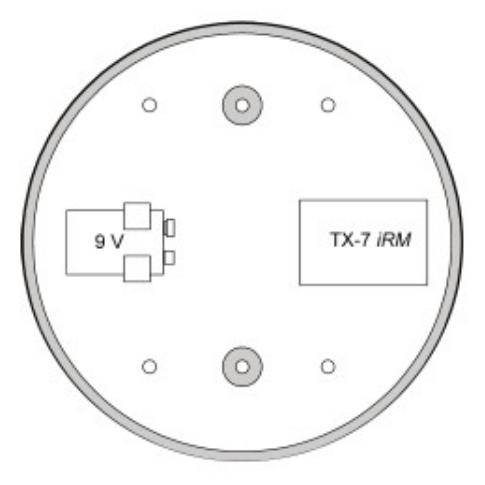
Battery and transmitter not included. Must be ordered separately.
Parts Included: 9V battery mounting clip (CM-69 only) 4 X 6-32 self-tapping screws
File: CM-69S & CM-47S Revised: March 17, 2009 Part No: 40-82B058