Camden CX_ED1309 Series Electric Strike Installation Instructions
Open the original PDF document
View PDF

Electrified Locks, Relays and Timers
CX-ED1309 Series
Electric Strike
INSTALLATION INSTRUCTIONS
THIS PACKAGE INCLUDES:
1-4 PIN power connector (12V)
1-4 PIN power connector (24V)
Faceplate(s) included
4- Wire nuts
2- #10 x 1 1/4" wood screws
4- #10-24 x 1/2" screws
2- Mounting brackets
1- Varistor
1- Dress Plate
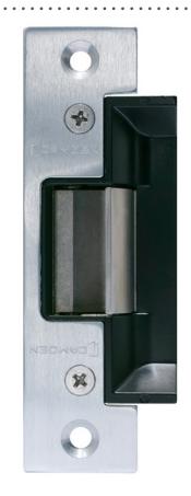

1. DESCRIPTION
Camden CX-ED1309 Series Grade 1 ANSI strikes for cylindrical locksets offer the very best strike quality and performance. The 'Universal' strike design delivers unparalleled application flexibility, with field selectable voltage, fail safe/fail secure operation for use in aluminum jambs and stiles.
2. SPECIFICATIONS
| Voltage | 12/24V AC/DC |
|---|---|
| Current Draw |
260mA@12V DC
150mA@24V DC |
| Static Strength | 1,500 Lbs. |
| Dynamic Strength | 70 Ft-Lbs. |
| Endurance |
1,000,000 Cycles (Factory Tested)
250,000 Cycles (UL Verified) |
| Mode |
Field Selectable
Fail Safe/Fail Secure |
| Operation | AC-Buzz, DC-Silent |
| Duty | Continuous |
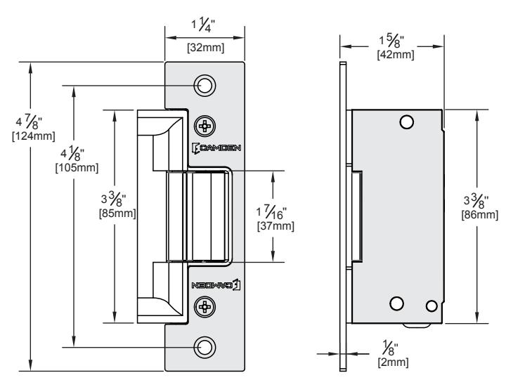
| Dimensions (Body) |
4 7/8" H x 1 11/16" W x 1 5/8" D
(124mm x 43mm x 42mm) |
UL 294 Performance Levels
- Line Security = Level I
- Attack Level = Level I
- Endurance Level = Level IV
- Standby Power = Level I
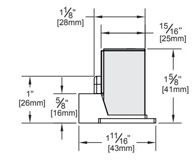
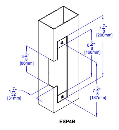
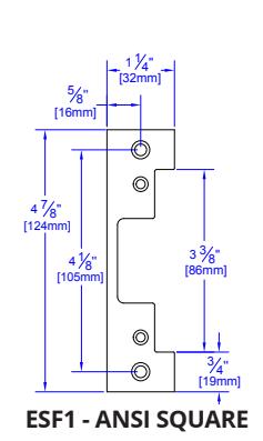
3. DIMENSIONS
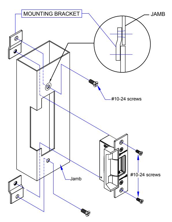
4. INSTALLATION
- 1. Prepare the door jamb as per the appropriate drawing.
- 2. Install mounting brackets to jamb using #10-24 screws and pressed metal nuts. Do not tighten.
- 3. Connect wires coming from the low voltage side of the transformer to wire (black) from strike.
VERTICAL CENTER LINE
Note: The products are intended to be installed in accordance with the installation wiring diagram, mechanical assembly drawings provided with each product, the local authority having jurisdiction (AHJ) and the electric code, NFPA 70. When installed in fail secure mode, the local authority shall be consulted with the regards to the use of possible panic hardware to allow emergency exit from the secure area.
The electric door strike shall be installed in such a way and in such a location so as to not impair the operation of an emergency exit device or panic hardware mounted on the door.
- 4. Install electric strike jamb by attaching #10-24 screws and lockwashers.
- 5. Secure #10-24 screws holding mounting brackets to jamb.
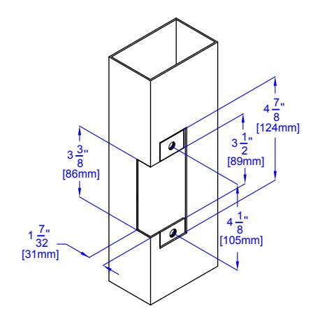
ESP1B + ESP2B
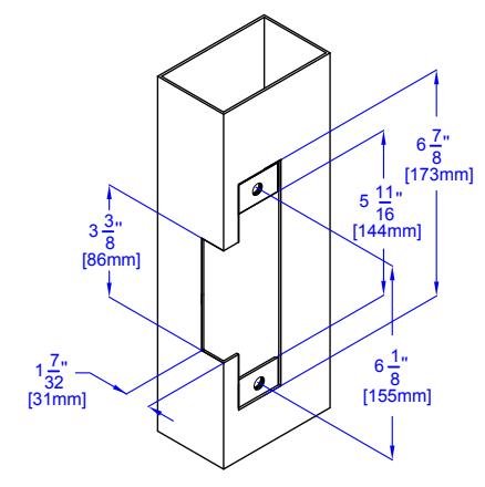
ESP3B
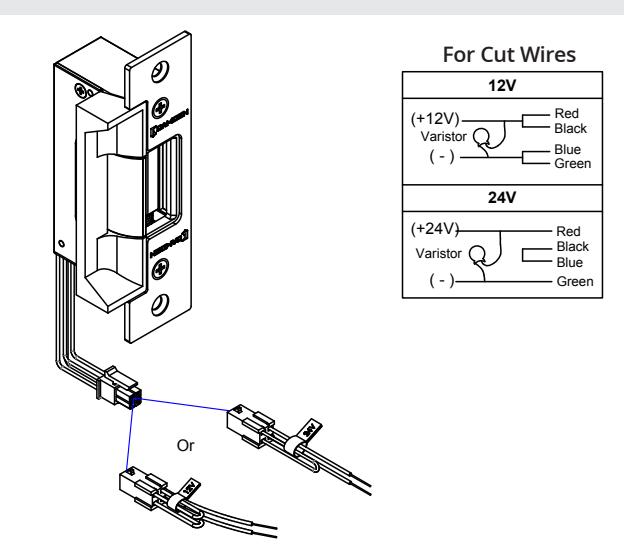
5. CONNECTIONS
POWER
12V AC/DC 24V AC/DC
Red/Black: +12V Red: +24V Blue/Green: Ground Black/Blue: -
Green: Ground
A varistor is provided to protect/prevent strike from spikes. Connect varistor between input wires.
Note: For UL 294 / UL 1034 compliance the door strikes are to be powered via a UL 294/ UL 603 class 2 power limited output from a control panel and or power supply. Furthermore, when powered by AC/DC the units shall use a UL regulated UL 294/ UL 603 power limited class 2 output rated 12/24V with AC on indicator.
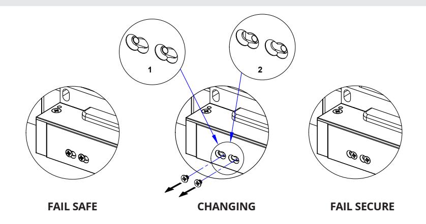
6. OPERATION
How to modify fail-safe to fail-secure or vice versa.
- Loosen and remove the screws as per the product diagram below
- 2. Slide internal mechanism to the right
- 3. Tighten the screws.
6. FACEPLATES
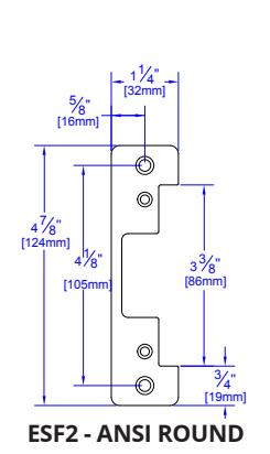
AVAILABLE FACEPLATES
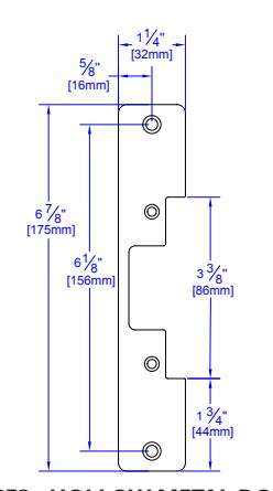
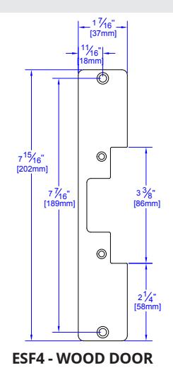
ESF3 - HOLLOW METAL DOOR

Certified ISO 9001: 2008
File: CX-ED1309 Electric Strike-R1.indd Rev. Label/Date: 04/10/19 Part No.: 40-82B231-A