Camden CX-ED2079 Universal Electric Strike Installation Instructions
Open the original PDF document
View PDF


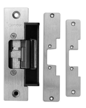
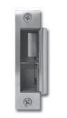
CX-ED2079 'Universal' Electric Strike
Installation Instructions
This Package Includes:
- 1- 4 PIN power connector
- 2- #10-32 x 1/2" screws
- 1- ESP1B, ESP3B and
- 2- Mounting brackets
- ESP4B faceplates
- 2- Spacers
- 4- Wire nuts
- 1- Varistor
- 5- M5 x 12mm screws
-
2- #10 x 1 1/4" wood
- screws
1. Description
Camden CX-ED2079 low profile grade 2 ANSI strike for cylindrical locksets offers the very best strike quality and performance, with three stainless steel faceplates provided. The 'Universal' strike design delivers unparalleled application flexibility, with field selectable voltage, fail safe/fail secure operation and mechanical adjustment of the strike body.
2. Specifications
| Voltage | 12/24V AC/DC |
|---|---|
| 300mA@12V DC | |
| Current Draw | 150mA@24V DC |
| Static Strength | 1,000 Lbs. |
| Dynamic Strength | 50 Ft-Lbs. |
| Endurance | 700,000 Cycles (Factory Tested) |
| 250,000 Cycles (UL Verified) | |
| Mode | Field Selectable |
| Fail Safe/Fail Secure | |
| Mech. Adjustment | Strike Body/Faceplate |
| Operation | AC-Buzz |
| DC-Silent | |
| Duty | Continuous |
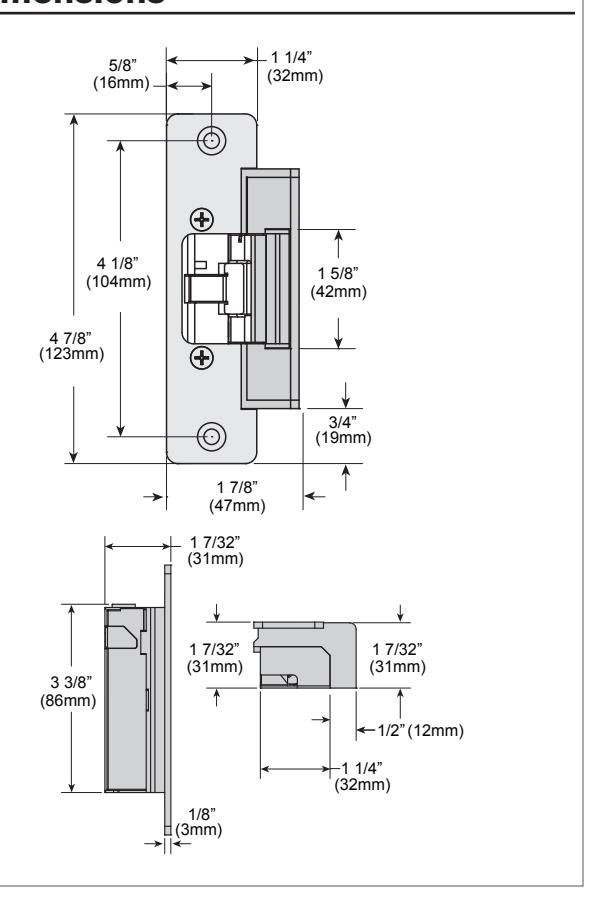
| Dimensions (Body) | 3 3/8" H x 1 7/8" W x 1 7/32" D |
| (86mm x 47mm x 31mm) |

UL 294 Performance Levels
- Line Security = Level I
- Attack Level = Level I
- Endurance Level = Level IV
- Standby Power = Level I
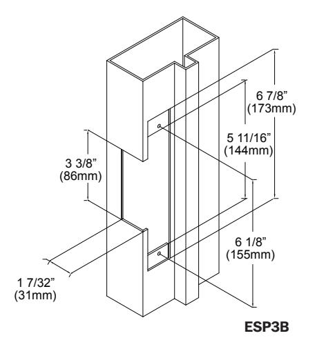
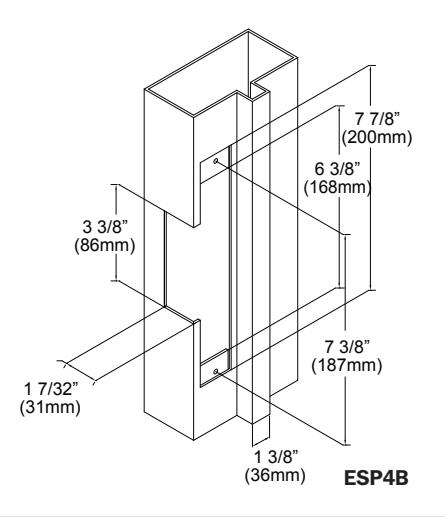
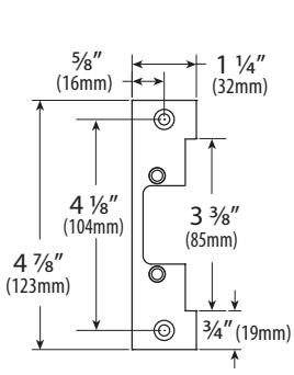
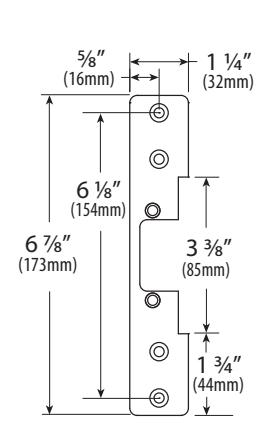
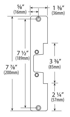
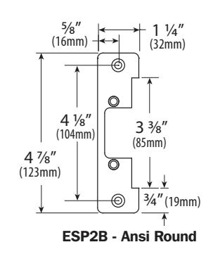
3. Dimensions
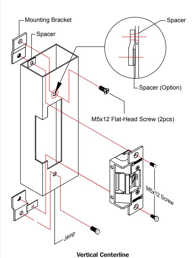
4. Installation
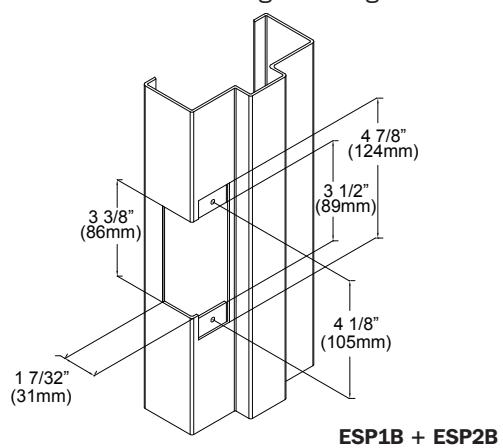
- 1. Prepare the door jamb as per the appropriate drawing.
- 2. Install mounting brackets to jamb using M5x12 screws and pressed metal nuts. Do not tighten.
- 3. Spacers are used to assure flush final assembly of faceplate into jamb. Add one of more spacers between jamb and mounting bracket when face plate extends beyond the jamb. When the faceplate sits inside the jamb, spacers must be added between the mounting
Note: The products are intended to be installed in accordance with the installation wiring diagram, mechanical assembly drawings provided with each product, the local authority having jurisdiction (AHJ) and the National Electric Code, NFPA 70. When installed in fail secure mode, the local authority shall be consulted with regard to the use of possible panic hardware to allow emergency exit from the secure area.
The electric door strike shall be installed in such a way and in such a location so as to not impair the operation of an emergency exit device or panic hardware mounted on the door.
- bracket & the lip bracket. Make sure clearance hole in spacer aligns with hole in mounting bracket.
- 4. Connect wires coming from the low voltage side of the transformer to wires (black) from strike.
- 5. Install electric strike jamb by attaching with # 10-32 screws and lockwashers.
- 6. Secure M5x12 screws holding mounting brackets to jamb.
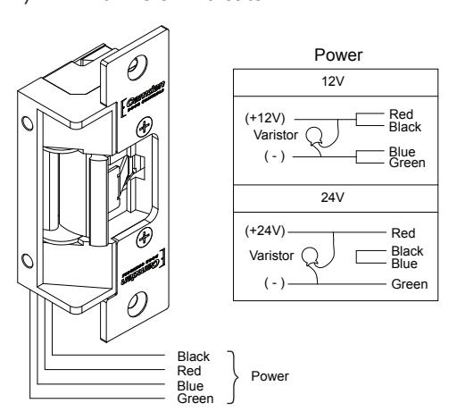
5. Connections
POWER 12VDC
Red/Black: +12V Blue/Green: Ground
24VDC
Red: +24V Black/Blue: -
Green: Ground
A varistor is provided to protect/prevent strike from spikes. Connect varistor between input wires.
Note: For UL 294 / UL 1034 compliance the door strikes are to be powered via a UL 294 / UL 603 class 2 power limited output from a control panel and or power supply. Furthermore, when powered by AC/DC the units shall use a UL regulated UL 294 / UL 603 power limited class 2 output rated 12/24V with AC on indicator.
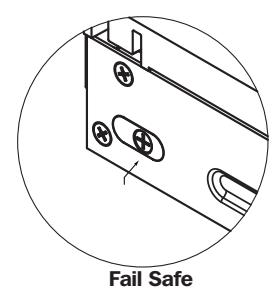
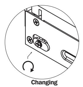
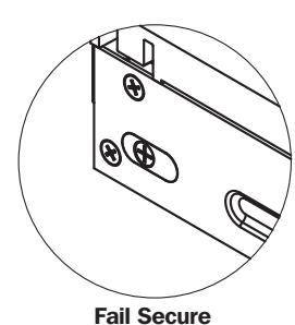
6. Operation
How to modify fail-safe to fail-secure or vice versa.
- (1). Loosen the screw as per the product diagram below.
- (2). Rotate the set plate 180 and slide the plate until it is properly seated.
- (3). Tighten the screw.
7. Faceplates
INCLUDED IN PACKAGE
ESP1B - ANSI Square
ESP3B - Hollow Metal Door
ESP4B - Wood Door
ADDITIONAL FACEPLATE
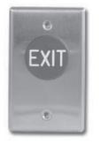
Push Buttons
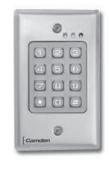
Keypads
Strikes
Magnetic Locks
Key Switches
Relays & Timers

Access Control

5502 Timberlea Blvd., Mississauga, ON Canada L4W 2T7
www.camdencontrols.com Toll Free: 1.877.226.3369
File: CX-ED2079 Designer Installation Instructions.indd R6 Revision: 01/06/2018 Part No.: 40-82B187