Camden CX-ED1259L Rim Electric Strike Installation Instructions
Open the original PDF document
View PDF

Electrified Locks, Relays and Timers
CX-ED1259L
'RIM' Electric Strike
INSTALLATION INSTRUCTIONS
THIS PACKAGE INCLUDES:
(1) 4-PIN power connector
(1) 3-PIN door status connector
(4) 14-20 x 1 1/2" screws
(2) 10-32 x 1" screw spacers
(4) 4-40 x 1/4" screws
(2) M5 self tapping screws
(1) MOV
(2) 1/8" S/S Spacers Plates
(1) Cover plate
(1) Install Jig
1. DESCRIPTION
Camden CX-ED1259-L Grade 1 RIM strike for pullman latches offers the very best strike quality and performance. The strike design delivers unparalleled application flexibility, with field selectable voltage, fail safe/fail secure operation and mechanical adjustment of the strike body.
2. SPECIFICATIONS
| Voltage | 12/24V AC/DC |
|---|---|
| Current Draw |
280mA@12V DC
140mA@24V DC |
| Static Strength | 1,500 Lbs. |
| Dynamic Strength | 70 Ft-Lbs. |
| Endurance |
1,000,000 Cycles (Factory Tested)
250,000 Cycles (UL Verified) |
| Latch Protection | 1/2" - 3/4" |
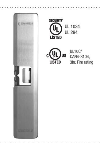
| Fire Rating |
UL 10C/CAN4-S104
3 hrs. (Fail Secure Only) |
| Mode |
Field Selectable
Fail Safe/Fail Secure |
| Mech. Adjustment | Strike Body |
| Operation | AC-Buzz, DC-Silent |
| Duty | Continuous |
| Latch Bolt Monitor | SPDT, 100mA @ 24V DC |
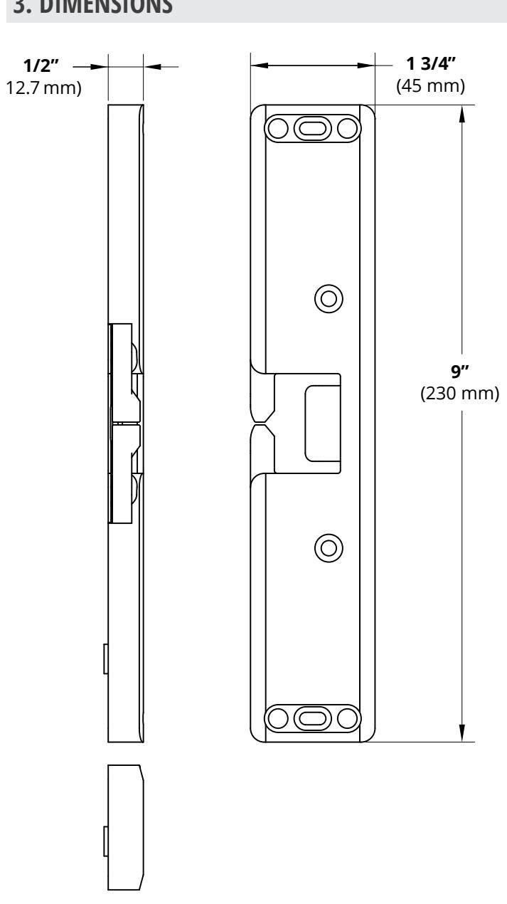
| Dimensions (Body) |
9" H x 1 3/4" W x 1/2" D
(230mm x 45mm x 12.7mm) |
3. DIMENSIONS
4. INSTALLATION
Introduction
RIM electric strikes, used with Pullman latch devices (i.e. crash bars) are very different from installing an electric strike for cylindrical or mortise locksets, and therefore require additional considerations and a different installation technique. In addition, Camden's CX-ED1259L RIM strike is unique from competitive brands of RIM electric strikes in two regards:
- CX-ED1259L requires the installer to use additional mounting screws. Although this may take more time during installation, the benefit is that once installed, Camden's RIM strike will not
move out of alignment (and require a service call) – a common occurrence with competitive RIM strikes.
- CX-ED1259L is the only ½" thick UL Fire listed RIM strike on the market. This means that spacer plates (supplied with the strike) will need to be used whenever the latch projection (throw) is over ½", up to ¾".
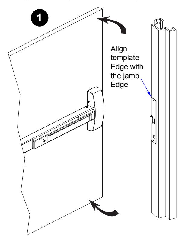
Step 1: Using the Install Jig
Note:
1. Open door slightly. Place template on door jamb aligning template edge with jamb edge.
Note:
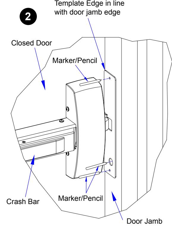
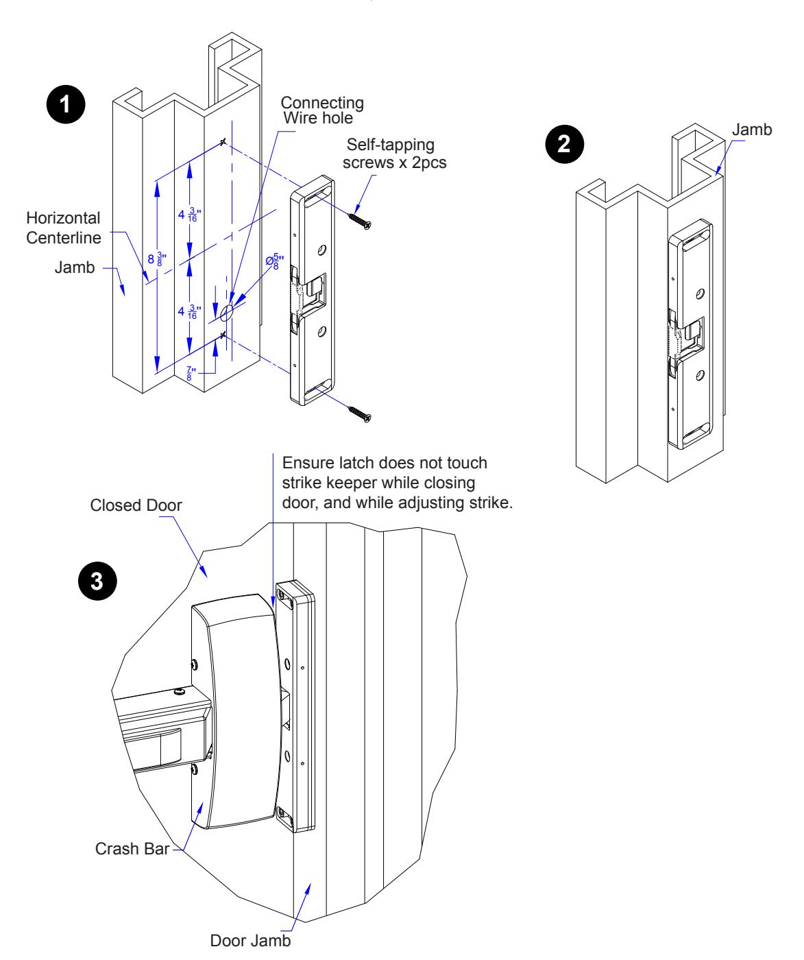
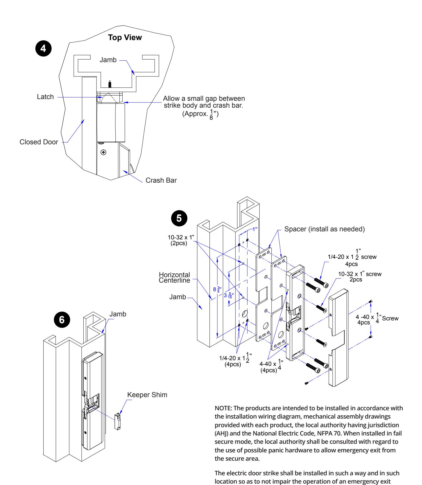
- 1. Close door making sure template is in place. Align Crash bar latch with Template latch hole.
- 2. Mark the hole centers on the frame with a pencil or marker.
Note:
1. Open door slightly, and remove the template.
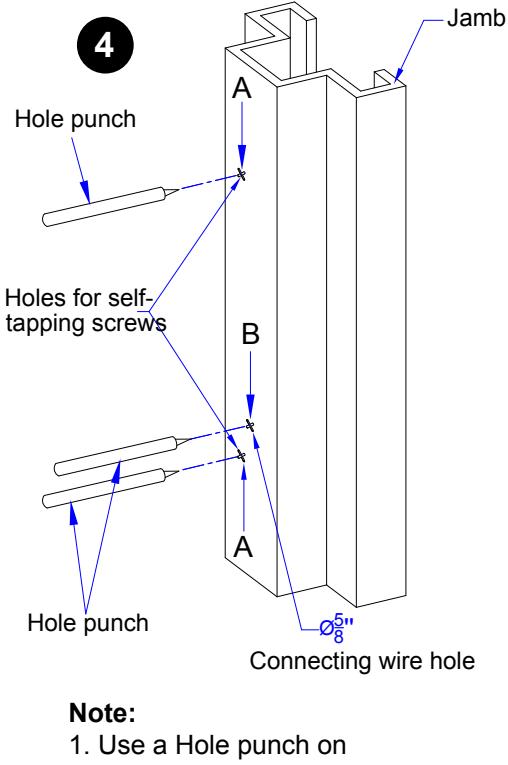
- Use a Hole punch on marked positions
- 2. Use drill size 5/8" to drill Hole B
- 3. Drill pilot holes on A for self tapping screw (Screw ")
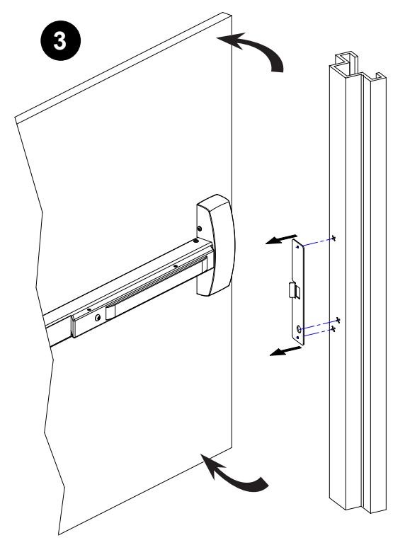
Step 2: Aligning the Strike
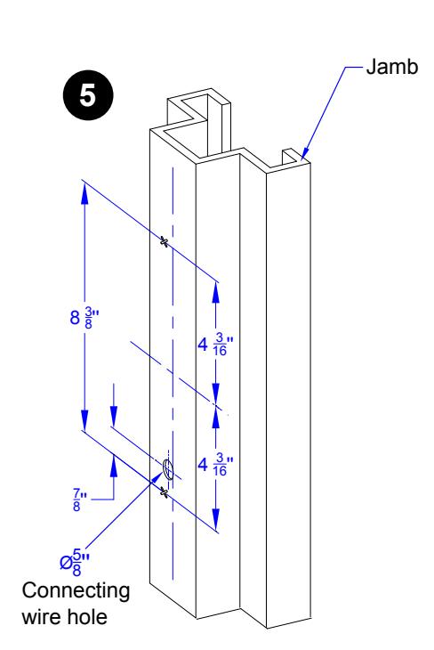
- 1. Using center line, measure 4 3/16" top and bottom, and drill Ø 5/8" hole for connecting wires, as per template.
- 2. Fix strike body with Ø 3/16" self-tapping screws.
- 3. Close door (Ensure crash bar latch does not touch keeper while closing the door). If necessary, adjust strike so that strike and crash bar latch are well aligned.
Note: the keeper jaws are fitted with a silicone shim. The crash bar should only touch this shim, not apply pressure when the door is closed.
- 4. While adjusting strike, allow a small gap between strike body and crash bar (approx. 1/8") Mark remaining screws position.
- 5. Open door and remove strike. Drill threads at screws positions.
- 7. Connect wires as per drawing.
- 8. Fix strike with remaining screws (1/4-20 x 1 ½" (4pcs) at both ends / 10-32 x 1(2pcs) in the middle)
- 9. Remove keeper shim.
device or panic hardware mounted on the door.
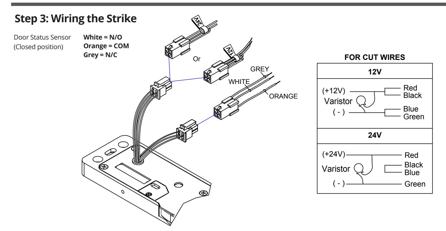
A varistor is provided to protect the strike from spikes. Connect the varistor between the input wires.
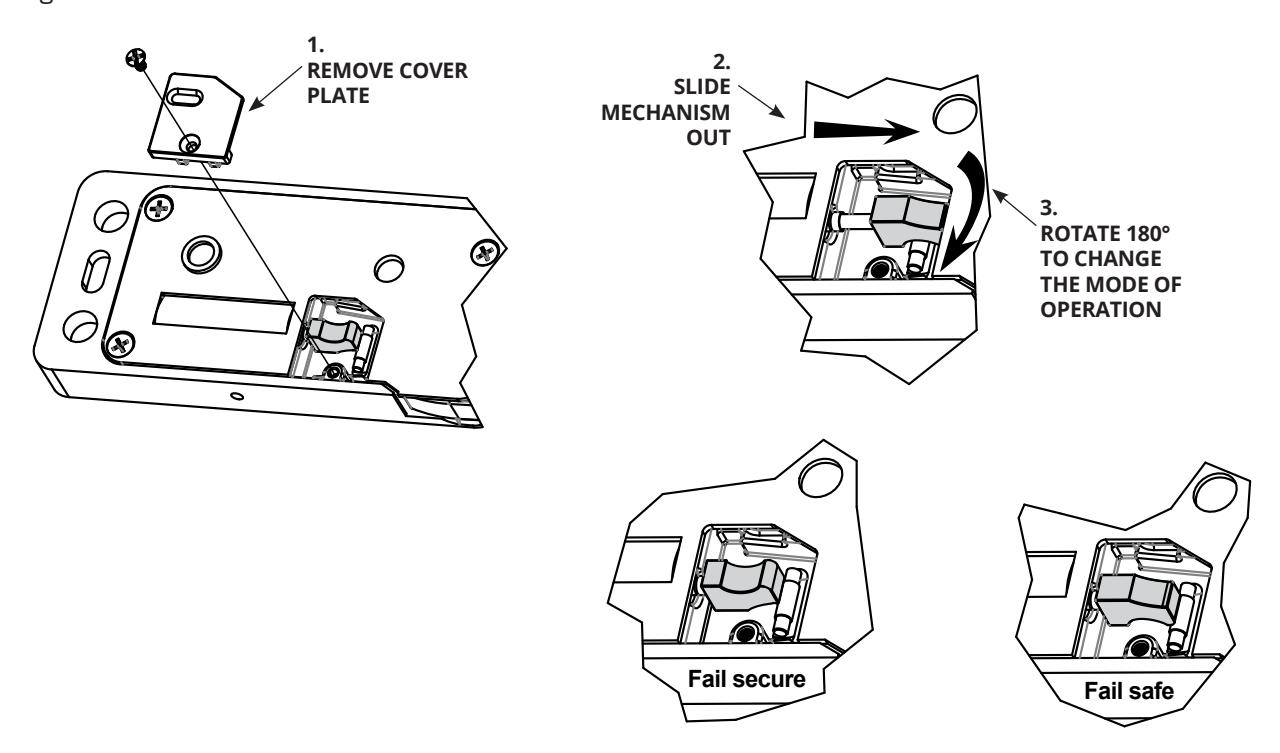
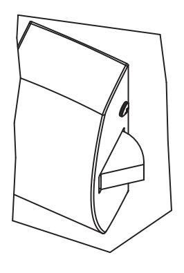
Step 4: Setting Fail-Secure/Fail Safe
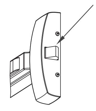
Product is factory set to fail secure. To change from fail secure to fail safe:
1. Loosen the screw at the back of the Electric strike as per the diagram below.
5. TROUBLESHOOTING
This guide has been produced to help installers understand the most important physical considerations that need to be addressed when installing the CX-ED1259L RIM strike.
Step 1 – Confirm Latch entry to rim strike
The position of the latch held by the RIM strike is of critical importance to the operation of the strike. The most important considerations, and potential causes of failure, are as follows:
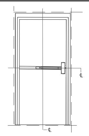
- The centerline of the keeper (jaws) of the RIM strike MUST line up with the centerline of the latch of the crash bar. Mark the centerline of the latch on the door frame, prior to mounting the strike, to provide a point of reference.
- The crash bar latch MUST NOT apply pressure on the keeper (jaws) of the RIM strike. Pre-load pressure on the jaws of the strike will prevent the strike from operating – and is the most common reason for a strike failing. Position the RIM strike so that the jaws of the strike are just lightly resting against the latch of the exit device.
- The exit device latch MUST depress (activate) the latch monitor 'paddle' of the RIM strike.
Even if the latch monitor is not used, this placement insures that the latch of the exit device is fully held by the keeper (jaws) of the strike.
(2) Spacer plates are provided with the CX-ED1259L RIM strike and are used as needed for this.
Step 2 – Confirm Door Alignment
Virtually all of Camden's electric strike models, including the CX-ED1259L RIM strike, offer horizontal adjustment, to compensate for doors that are misaligned with the door frame– but there is a limit to the strike adjustment.
• Check that the door is not binding on the frame. An electric strike cannot compensate for this. If present, the door hinges will need to be adjusted.
• Check the gap between the door and the stop of the frame (where the top and at the bottom of the door. A ¼" difference in gap is very common and can be compensated for by the strike – IF INSTALLED CORRECTLY.
If the door stop gap at the top and bottom of the door is different, the electric strike cannot be installed plumb ('straight' up and down) . The horizontal orientation of the RIM strike will need to be adjusted to match the angle of the misaligned door. To do this:

- Mount the RIM strike in position on the frame, using only the (2) center (elongated) screw holes , top and bottom.
- Rotate the strike until both jaws of the strike very lightly touch the crash bar latch, with equal gap, on both jaws.
- Tighten the center screws and open/close door to confirm that the latch does not bind on the jaws of the strike.
- After this is done, you can then affix the 6 screws that permanently mount the strike on the frame.
Other Considerations
Although the considerations above will address the majority of installation steps needed for a successful installation, there are a few additional items that you will need to check for:
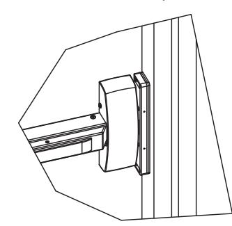
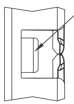
• Consideration for deadlocking latch (as shown here) If the exit device has a deadlocking latch, the CX-ED1259L RIM strike must be mounted so that the deadlocking latch does not enter the latch cavity of the RIM strike.
Position the strike so that the deadlocking latch rests against the face of the strike.
Consideration of the free movement of the exit device latch and the keeper (jaws) of the RIM strike.
Ensure the latch of the exit device and the keeper (jaws) of the electric strike have free and easy movement to operate together, with a minimum of friction. In this, a small amount
of silicone lubricate on both the latch and jaws of the strike will improve the operation… but please be careful not to over spray.
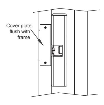
Consideration for a professionally finished retrofit installation.
Replacing electric strikes used with cylindrical or mortise locksets, with an exit device and RIM strike, will leave holes in the door and door frame that must be filled or covered. Cover or plug holes and check that new cover plates are
flush with the frame… and will not interfere with the RIM strike.
Summary
Adherence with the recommendations of this guide will avoid the most common problems associated with the installation of RIM strikes. If you require additional assistance, please contact our Technical Support department by phone at 1 877 226-2269 or email support@camdencontrols.com.

Call: 1.877.226.3369 / 905.366.3377 Visit: www.camdencontrols.com