Camden CX-DA-400 Door Prop Alarm Installation Instructions
Open the original PDF document
View PDF


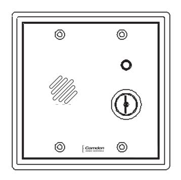
CX-DA400 Door Prop Alarm
Installation Instructions
CONTENTS
DESCRIPTION
The CX-DA400 provides complete monitoring of access control points by offering you prop/door held open and intrusion/door forced open detection. These alarms are designed to complement card reader and access control systems and will interface with electronic locks, produce audible warnings and reduce nuisance alarms by encouraging user compliance with access control procedures.
OTHER FEATURES
- Shunt Recycle See Step 3. Pg. 4
- Door Supervision See Step 1. Pg. 3
- Intrusion Detect See Step 2. Pg. 3
- Loud Horn Volume See Step 7. Pg. 5
- Extended Silent Time See Step 4. Pg. 4 • Shunt Delay Timer - See Step 4 . Pg. 4
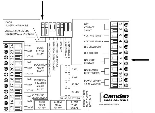
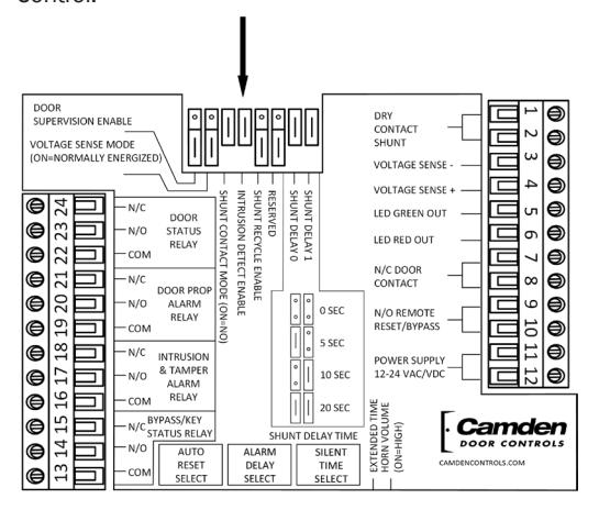
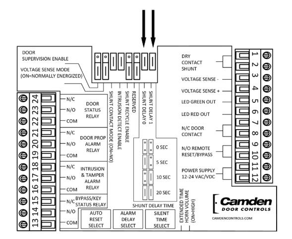
COMPONENT LOCATION DIAGRAM
OUTPUTS
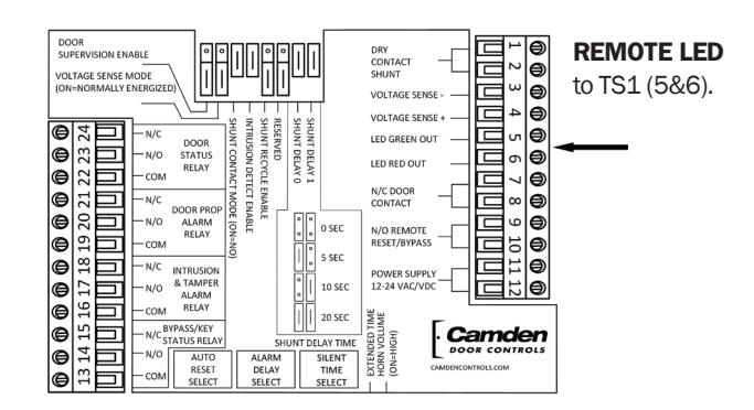
- • Remote LED (located on TS-1) Output for a remote Bi-color LED, output follows LED on Face Plate.
- • Door Status Relay follows the Door Contact Input, regardless of alarm or bypass condition.
- • Door Prop Alarm Relay changes state during a Door Prop (Door Held) Alarm condition.
- • Intrusion & Tamper Alarm Relay changes state during an Intrusion or Tamper Alarm condition.
- • Bypass/Key Switch Status Relay follows Bypass and Key inputs.
Output contacts change state when power is lost.
INPUTS
The inputs are located on Terminal Strip –1 and include:
- • Dry Contact Shunt a N/O or N/C Dry Contact, selected using Shunt Contact Mode Jumper 3. See Step 3. Pg. 4
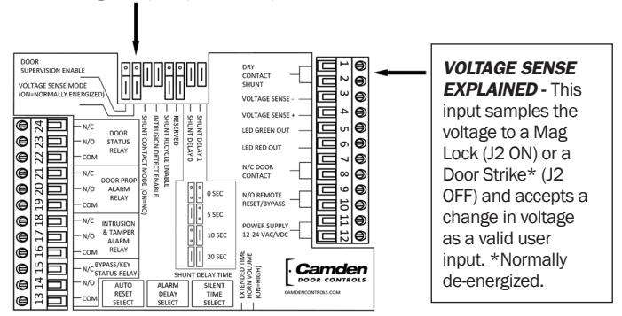
- • Voltage Sense Monitors the power wires on an electric lock (i.e.: Mag-lock or Door Strike). Senses change in voltage as valid user. See Step 3. Pg. 4
- • Door Contact a Closed Loop (N/C) Dry Contact which opens when the monitored door opens. See Step 1. Pg. 3
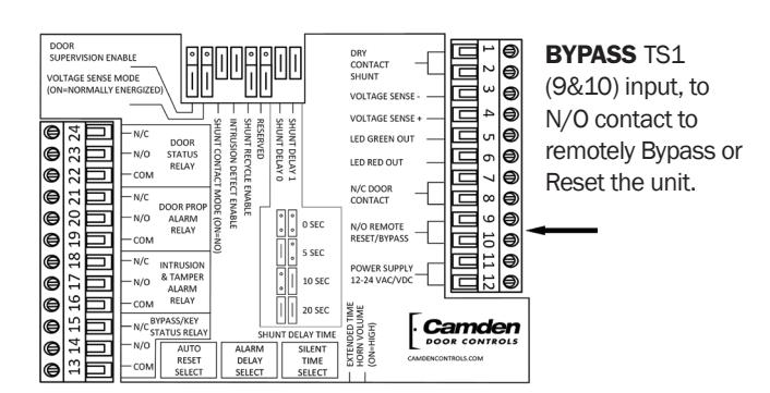
- • Bypass Connect to a N/O Dry Contact from a remote location to bypass the unit. See Step 7 Pg. 5
- • Power 12 to 24 VAC/DC @ 250 mA. The terminals are not polarity sensitive. See Step 5. Pg. 4
| JUMPER | CONFIGURES | |
|---|---|---|
| 1 Door Supervision (Part of Tamper circuit) | TS1-7&8 Door Input | |
| 2 Voltage Sense Mode (Senses Lock Voltage as Valid User Input) | TS1-3&4 Voltage Sense Input | |
| 3 Shunt Contact Mode (Senses Dry Contact as Valid User Input) | TS1-1&2 Shunt Contact Input | |
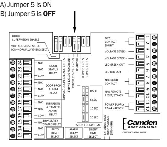
| 4 Intrusion Detect Enable (Explained on reverse) | Intrusion or Free Access selection | |
| 5 Shunt Recycle Enable (Explained on reverse) | Shunt Recycle feature selection | |
| 6 RESERVED (Factory Diagnostic) | Factory Use Only Leave Jumper OFF | |
| 7 & 8 Shunt Delay Timer (Set same as Lock Time) | Access Time prior to opening door | |
| 9 Extended Time | Select Ext. Silent Time 3-90 Min. | |
| 10 Horn Volume | Select 96db or 103db | |
TIMERS
- • Silent Time "Open Door" Time 0-2.5 min. in standard mode, 3 - 90 min. in Extended mode (selected by Jumper 9).
- • Alarm Delay "Warning" Time 0-5 min. and "Infinite." Local Beeping Warning Audible sounds during this time.
- • Auto Reset "Alarm" Time 0-5 min. and Manual Reset. Constant Alarm Audible sounds during this time.
- • Shunt Delay Valid Access Time prior to reset if Door is unopened. 0, 5, 10, or 20 seconds (set with Jumpers 7 & 8).
TIMER SETTING TABLE SIDE VIEW
|
SILENT TIME
SELECT (Extended Silent Time Jumper) |
ALARM
DELAY |
AUTO
RESET |
|||
|---|---|---|---|---|---|
| SET |
NORMAL
Jumper OFF |
EXTENDED
Jumper ON |
TIME
SELECT |
TIME
SELECT |
|
| 0 | 0 Sec | 3 Min | 0 Sec | 0 Sec | |
| 1 | 3 Sec | 3.5 Min | 3 Sec | 3 Sec | |
| 2 | 5 Sec | 4 Min | 5 Sec | 5 Sec | |
| 3 | 7 Sec | 4.5 Min | 7 Sec | 7 Sec | |
| 4 | 10 Sec | 5 Min | 10 Sec | 10 Sec | |
| 5 | 12 Sec | 6 Min | 12 Sec | 12 Sec | |
| 6 | 15 Sec | 7 Min | 15 Sec | 15 Sec | |
| 7 | 20 Sec | 8 Min | 20 Sec | 20 Sec | |
| 8 | 25 Sec | 9 Min | 30 Sec | 30 Sec | |
| 9 | 30 Sec | 10 Min | 45 Sec | 45 Sec | |
| A | 35 Sec | 20 Min | 1 Min | 1 Min | |
| B | 45 Sec | 30 Min | 2 Min | 2 Min | |
| C | 1 Min | 40 Min | 3 Min | 3 Min | |
| D | 1.5 Min | 50 Min | 4 Min | 4 Min | |
| E | 2 Min | 60 Min | 5 Min | 5 Min | |
| F | 2.5 Min | 90 Min | INFINITE | MANUAL | |
TAMPER CIRCUIT- Alarm is not reset with key. (CX-DA401 only)
- • TAMPER SWITCH Switch is located on stand-off under spring steel actuator. (Cut cable tie to Enable switch)
- • DOOR SUPERVISION Enable with Jumper 1. Requires resistors on Door Switch. (Schematic on Step 1 Pg.3)
OPERATION
VALID ACCESS / PROPPED DOOR OPERATION
ARMED STATE - Red LED (Green if Intrusion Detect is Off) VALID USER INPUT - Shunt or Voltage Sense Input
LED - Changes to Green
DOOR - Opened by user, Silent Timer begins
DOOR - Closed by user, Returns to Armed State, or
- SILENT TIME TIMER - expires, then
AUDIBLE WARNING - Beeps to alert user locally
LED - Flashes Green
DOOR - Closed by user, returns to Armed State, or*
- SHUNT RECYCLE - 2nd Valid User Input (*if enabled)
SILENT TIME RESET - Silent Timer begins again
DOOR HELD/PROPPED - Alarm Delay Times out
LED - Flashes Red
AUDIBLE - Constant tone, Auto Reset (AR) Timer begins
OUTPUT - Door Prop Alarm relay toggles
DOOR CLOSED - After Door Prop Alarm exists
AUDIBLE - On until Auto Reset (AR) Time expires
LED - Flashes Red for AR Time
OUTPUT - Relay held for duration of AR Time
INTRUSION OPERATION
ARMED STATE - Red LED
DOOR Opened by invalid entry
LED - Flashes Red
AUDIBLE - Constant tone, Auto Reset (AR) Timer begins
OUTPUT - Intrusion/Tamper Alarm relay toggles
- DOOR CLOSED
LED - Flashes for duration of AR Time
AUDIBLE - Continues for duration of AR Time
OUTPUT - Changed for duration of AR Time
- REARM - After AR time expires OR by Manual reset
LED - Red (Armed State)
TAMPER OPERATION (CX-DA401 only)
ARMED STATE - Red LED (Door Supervision Enabled)
- TAMPER (Door circuit open/shorted, or if unit is removed from wall)
LED - Flashing Red
AUDIBLE - Constant tone
OUTPUT - Intrusion/Tamper Alarm relay toggles
- RESET - Door normal, and Tamper switch closed LED - Red (Armed State)
CM-324 Active Infrared "Hands-Free" Switch Installation Instructions CX-DA400 Door Prop Alarm Installation Instructions
STEP BY STEP INSTRUCTIONS FOR EASY CONFIGURATION
THE DEFAULT SETUP IS FOR ACCESS CONTROLLED, AND EMERGENCY EXIT APPLICATIONS.
- This unit may be connected to power and a closed-loop Door Input and be ready to work immediately for the Default application.
- A Voltage Sense input used with a Mag-Lock, and/or a N/C Dry Contact Shunt input will require additional jumper configuration (J2 and/or J3 respectively) and is covered in Step 3 Pg. 4.
- The unit is easily configured for a stand-alone Door Prop application by removing the Intrusion Detection jumper. (LED will always be Green when Intrusion Detection is disabled.)
TIMER SETTING DEFAULTS: (Step 4 Pg.4)
- Silent Time 5 seconds;
- Alarm Delay Time 5 seconds
- Auto Reset Time 5 seconds
- Shunt Delay 20 seconds
See text for Feature Description and Setup info.
TERMS USED IN THIS INSTRUCTION
N/C DOOR CONTACT - is a "closed-loop" circuit which goes open when the door is opened.
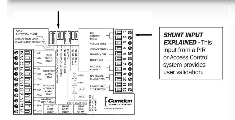
SHUNT INPUT - is a dry contact Valid User Input provided by an Access Control System or a PIR / REX device.
DMA - Door Management Alarm (i.e.: CX-DA400)
Normally Energized - in reference to a Mag-Lock or other locking device where power is removed to unlock.
Normally De-energized - in reference to a Door Strike or other locking device where power is applied to unlock.
1 DOOR SUPERVISION, AND TAMPER
- Connect N/C Door Contact to TS1 7&8.
- If resistors are installed for Door Supervision:
A) place Jumper 1 ON and put resistors at door switch as shown in Figure 1.
B) If unused, leave Jumper OFF and use a closed-loop Door Switch circuit.
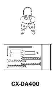
CX-DA400
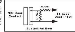
Figure 1
• Tamper Alarm (cannot be reset or bypassed) A) To Enable feature cut cable tie on Tamper Switch located on standoff (Component Location on reverse. (CX-DA401 only)
2 INTRUSION DETECTION
A) Jumper 4 is ON for Access Control and Emergency Exit Only applications.
B) Jumper 4 is OFF for Door Prop/Held applications without Access Control.
NOTE: If OFF, LED is Green except during a Door Prop Alarm. If OFF, Go to Step 4-Timer Settings. (Skip Step 3)
3 ACCESS CONTROL
• VOLTAGE SENSE monitors Lock Power as "Valid User" input on TS1 (3&4)
A) If unused, Jumper 2 must be OFF.
B) If used, select: Normally Energized (Jumper 2 ON); or, Normally De-Energized (Jumper 2 OFF)
• SHUNT INPUT detects a Dry Contact input for each valid access. TS1 (1&2)
A) If unused, Jumper 3 must be ON
B) If used, Select:
Jumper 3 ON for N/O input; or Jumper 3 OFF for N/C input
CX-DA400 Door Prop Alarm Installation Instructions
• SHUNT RECYCLE (see description below)
SHUNT RECYCLE EXPLAINED -
- When Shunt Recycle is Enabled (ON), a Shunt Contact or Voltage Sense Input during the Alarm Delay warning period (beeping) will reset the Silent Time Timer. Shunt Recycle gives the User the ability to Hold the door indefinitely by repeating a valid input during each Alarm Delay warning.
- When disabled, only a Key or Bypass input will reset the DMA.
4 TIMER SETTINGS SEE TABLE ON REVERSE
-
The SHUNT DELAY TIMER begins after a Valid User input (prior to door being opened) and
if door is not opened
the DMA will reset when timer expires. Cancels upon door opening.
- A) Shunt Delay works only with Intrusion Detection enabled.
- B) See table on Back Plate for Jumper 7&8 setting detail.
• SILENT TIME SELECT begins when the door is opened
by a valid user. (see Timer Setting Table on reverse)
- A) Timer has two ranges selected with Jumper 9;
- Normal 0 seconds to 2.5 minutes (Jumper OFF)
- Extended 3 minutes to 90 minutes (Jumper ON) B) After selecting appropriate range, turn dial to SET # for the Silent Time period desired for your application.
- • ALARM DELAY SELECT begins on the expiration of the Silent Timer. Warning Alarm sounds locally to alert user. A) Turn dial to SET # on table (see reverse) for the time
you want the Warning (beeping) alarm to sound (prior to triggering the Door Prop Alarm Horn and Relay).
• AUTO RESET TIME SELECT is the minimum time the Horn, LED and Relays are on following an alarm condition.
NOTE: Alarm will continue for as long as the door is open A) Turn the dial to SET Timer (0 seconds to 5 minutes, or Manual).
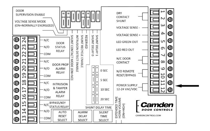
5 POWER
• POWER - Connect 12-24 VAC/DC to TS1 11&12. Not polarity sensitive.
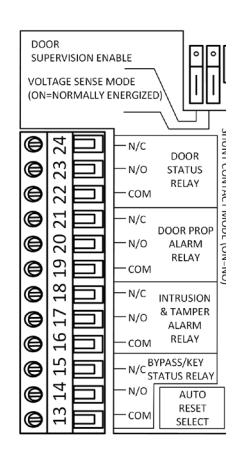
6 OUTPUTS (FORM-C)
• DOOR STATUS RELAY
TS2-22,23,24 changes state when the Door Input changes. Used to monitor changes in Door Contact status.
• DOOR PROP ALARM RELAY TS2-19,20,21 changes state when a door is held open beyond the Silent and Alarm Delay time, combined.
• FORCED DOOR/TAMPER ALARM RELAY
TS2-16,17,18 changes state when a door is forced or a tamper condition exists (Door Supervision/Tamper Switch).
• BYPASS/KEY SWITCH STATUS RELAY
TS2-13,14,15 changes state during Bypass (TS1 9&10) and Key Switch Inputs. Used to monitor for changes in Bypass status.
CX-DA400 Door Prop Alarm Installation Instructions
ADDITIONAL OUTPUT INFORMATION
• Each of the Output functions offers the availability of monitoring a Normally Open or a Normally Closed Dry contact.

• Each contact's state will change to follow the status of the monitored function.
• To combine multiple outputs, connect N/O contacts in parallel, or N/C contacts in series. See diagrams at right. The use of any/all Outputs is optional.
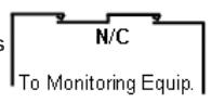
• If power is removed from the CX-DA400, each contact in it's normal state (powered), will change state. Example: Door Status will appear as if the door
has been opened; Alarm and Bypass contacts will appear as if an alarm or bypass condition exists.
ADDITIONAL FEATURES SEE COMPONENT LOCATION DIAGRAM ON PAGE 2 7
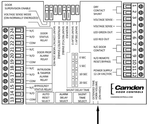
HORN VOLUME - Jumper 10 is used to set the volume of the sounder. ON = 103db
OFF = 96db
TROUBLE SHOOTING TIPS
- • Horn won't Reset Verify Tamper Switch is closed; Verify Door Supervision Jumper is correct for application; Check Door Contact Resistors are installed as per Step 1 if Door Supervision is enabled.
- • LED always Green Normal condition when Jumper 4 is OFF; Verify Shunt Contact & Voltage Sense jumpers are correct for your application; Verify Key Switch is Vertical and Bypass Input is open.
- • Alarm when Door Opens Verify that SO&S1 Jumpers and Silent Time are set greater than 0 sec.; Verify Intrusion Jumper is set correctly for application.
- • Clicking Output Relays Verify Jumper 6 (Reserved) is OFF.
| ELECTRICAL SPECIFICATIONS | |||||||
|---|---|---|---|---|---|---|---|
| VOLTS | AMPS | N/O | N/C | ||||
| Power | 12-24 VAC/DC | 250mA | N/A | ||||
| Voltage Sense | 12-24 VAC/DC | 15mA | |||||
| Shunt Input | Dry Contact | Jumper Select | |||||
| Bypass Input | Dry Contact | ✔ | |||||
| Door Input | Dry Contact | ✔ | |||||
| Output Relays | Dry Contact |
1 Amp@
30 VDC |
✔ | ✔ | |||
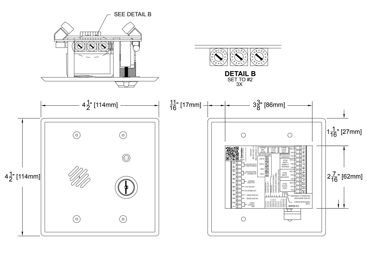
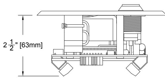
MECHANICAL SPECIFICATIONS
• The CX-DA400 mounts flush in a 2.5" (63 mm) deep, 2-Gang electrical box.
TECHNICAL DRAWING

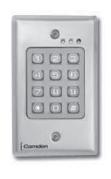
Keypads
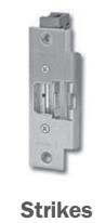

Key Switches

Relays & Timers


www.camdencontrols.com Toll Free: 1.877.226.3369
File: CX-DA400 Installation Instructions.indd- Rev1 Revised: June 9th, 2014 Part No: 40-82B157