Camden CX-91M-06 Installation Instructions
Open the original PDF document
View PDF

Mississauga, Ontario L4W 2T7 905-366-3377 Toll Free: 877-226-3369 www.camdencontrols.com
CX-91M-06 Installation Instructions 5502 Timberlea Blvd.
| Model | Description | Features | Current Draw |
|---|---|---|---|
| CX-91M-06 | Single | Basic | 480mA @ 12V |
| CX-91M-06TDS | Single |
adj. timer, door position
switch & bond sensor |
240mA @ 24V |
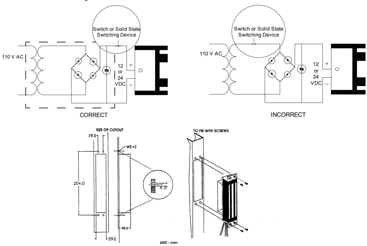
SHOCK HAZARD. Care must be taken to keep the power supply and wiring isolated from ground (earth). Use of an ohmmeter to test for shorts is recommended prior to service.
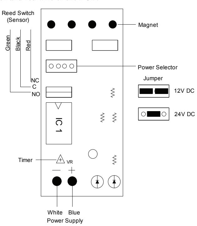
A. 12V DC Input:
Set jumpers for 12V DC operation. (See diagram below) Connect the ground (-) lead from a 12V DC power source to terminal 2. Connect the positive (+) lead from a 12V DC power source to terminal 1.
B. 24V DC Input:
Unit is delivered from Factory with single jumper ON for 24V operation. Connect the ground (-) lead from a 24V DC power source to terminal 2. Connect the positive (+) lead from a 24V DC power source to terminal.
C. Contacts:
Reed switch dry contacts are rated 0.5 Amp@30V DC/AC. For safe operation, do not exceed this rating. If you normally require a normally open contact, connect to the black and green wire of the PCB. If you normally require a normally closed contact, connect to the black and red wire of the PCB.
Printed Circuit Board Schematic
(shown with all options)
Important
Power switch should always be wired as shown below in order to minimize the effect of residual magnetism. Contact Camden for other wiring considerations.