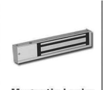
Camden CX-90S-03 Magnetic Lock 300 Lbs Surface Mount Single Door Installation Instructions
Open the original PDF document
View PDF


CX-90S-03 Magnetic Lock 300 Lbs Surface Mount, Single Door Installation Instructions
| Model | Description | Features | Current Draw |
|---|---|---|---|
| CX-90S-03 | Single | Basic |
360 mA @ 12VDC
180 mA @ 24 VDC |
SHOCK HAZARD. Care must be taken to keep the power supply and wiring isolated from ground (earth). Use of an ohmmeter to test for shorts is recommended prior to service.
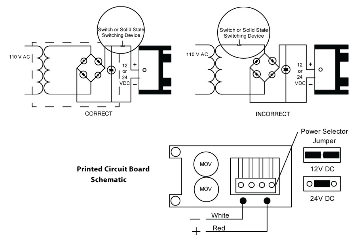
A. 12V DC Input:
Set jumpers for 12V DC operation. (See diagram below) Connect the ground (-) lead from a 12V DC power source to terminal 2.
Connect the positive (+) lead from a 12V DC power source to terminal 1.
B. 24V DC Input:
Unit is delivered from Factory with single jumper ON for 24V operation. Connect the ground (-) lead from a 24V DC power source to terminal 2. Connect the positive (+) lead from a 24V DC power source to terminal.
Note: Only use UL/CUL Listed Regulated Power Limited Power Source.
Important
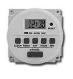
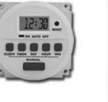
Power switch should always be wired as shown below in order to minimize the effect of residual magnetism. Contact Camden for other wiring considerations.
Important! Please read before installation
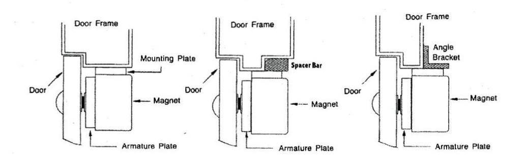
- A. Handle the components with care. Damaging the surfaces of the magnet or armature plate may reduce locking efficiency.
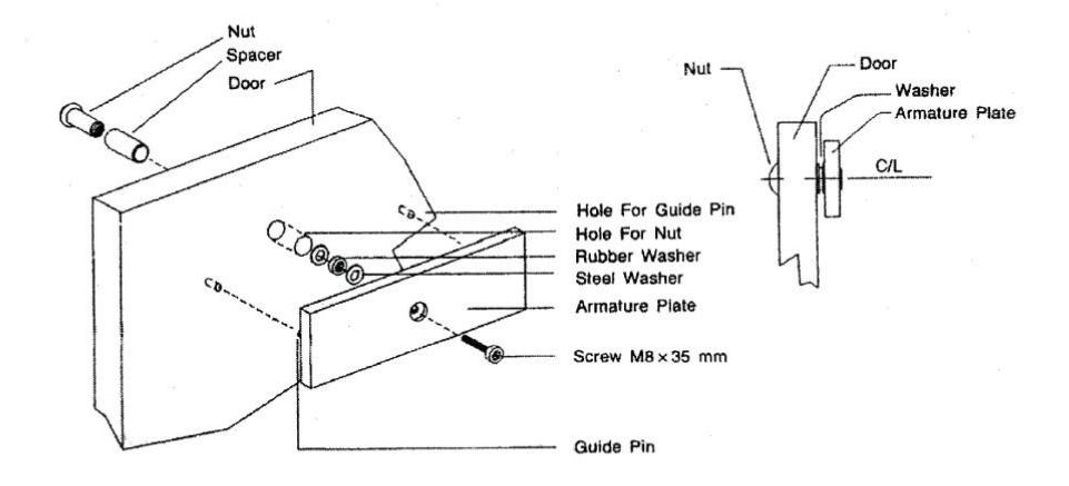
- B. The magnet mounts to the door frame. The armature plate must be mounted to the door with the hardware supplied. This allows it to pivot about its center to compensate for door wear and misalignment.
- C. Affix template with the door in its normally closed position.
- D. Mark and drill holes. Mount magnet and armature plate with screws installed finger tight at first. Verify all parts align correctly, and then firmly tighten screws.


5502 Timberlea Blvd., Mississauga, ON Canada L4W 2T7
File: CX-90S-03_Man_NF-Rev1.doc Revised: May 12, 2010 Part No.: 40-82B112
www.camdencontrols.com Toll Free: 1.877.226.3369