Camden CV-626SW Installation Instructions
Open the original PDF document
View PDF


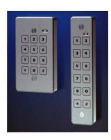
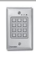
CV-626SW
Installation Instructions
Protocol: Wiegand 26 Power Supply: 12 VDC
Power Standby Consumption: less than 30 mA
Mounting: Single Gang Switch Box, or directly to the wall.
Environment: IP68; 100% relative humidity
Temperature: - 40° to + 70°C
CLICK-N-LOCK mounting screws protection
26 BIT WIEGAND SPECIFICATIONS WIRING
| COLOR | FUNCTION | ELECTRICAL FUNCTION |
|---|---|---|
| RED | Input Voltage | 8 - 24 VDC |
| BLACK | Ground | |
| GREEN | Data 0 | Open collector 1Kohm pull-up to internal +5V |
| WHITE | Data 1 | Open collector 1Kohm pull-up to internal +5V |
| BROWN | LED Input | Do not apply voltage |
| BLUE | CCTV output | Open collector 0,250 A activated with each key for 30 sec |
| VIOLET | Housing Ground | |
| ORANGE | Buffered Input | "Low" = Hold |
| GREY | Tamper Output | Open collector 0.25 A "Low" when light sensed |
When the LED control input is pulled low, the GREEN LED will be ON and the RED LED will be OFF. When the input goes high the RED LED is ON and the GREEN LED is OFF. The RED LED will flash with each key press. The LED control input is pulled to the internal +5v with a 2.2K resistor.
The data is sent at 1 msec per bit with a pulse duration of 50 µsec. A Buzzer beeps with each key press. The following WIEGAND output is sent each time the # (enter) key is pressed.
PSSSSSS NNNNNNNNNNNNNN P
BIT 12 9 10 25 26
BIT 1 is an even parity for the following 12 bits. The sum of bits 1-13 is even.
BITS 2-9 are the programmable SITE CODE. Pressing * during the first 3 seconds on unit's power up
It is possible to program the site code. Any number from 000 to 255.
BITS 10-25 this is the number entered prior to pressing # (enter).
Leading 0's are added as required. Bit 10 is most significant.
BIT 26 Odd parity over previous 12 bits. The sum of bits 14-26 is odd.
EXAMPLE: A code of 123 entered: 1 0 0 0 0 0 1 0 0 0 0 0 0 0 0 1 1 1 1
The data is sent at 1 msec per bit with a pulse duration of 70 usec. A Buzzer beeps with each key press.
CV-626SW Installation Instrutions
Notes:
- 1. Wiegand keypads are programmed with the default Site Code "000".
- 2. To set the Site Code:
- a. Disconnect the power supply for 10 seconds minimum.
- b. Connect the power supply.
- c. During the first 3 seconds perform the following:
i. Enter * The keypad enters programming mode. The LED flashes yellow.
ii. Enter: New Site Code The new site code is assigned.
3. Blue Wire: PRESSING any key on the keypad will generate a 30 second 0.25 amp intermittent duty grounding output.
- 4. Orange Wire: When the orange wire is pulled 'LOW', CV-626SW is in 'Hold' state: Any codes entered on the keypad are stored in the buffer and the LED turns YELLOW. When the Hold Line is released to logic 'HIGH', the buffered code data is sent.
- 5. Grey Wire: When the light sensor senses ambient light the wire is pulled 'LOW'.
- 6. An error code is generated by any of the following:
- a. Pressing the # key with no preceding digits.
- b. Pressing any number of only zero's prior to pressing the #key.
- c. Pressing 65535 or any number above 65535.
- 7. An error code will send all 1's to your panel. Do NOT program your panel to accept the code number 65535.
Questions? Call us toll-free at 1-877-226-3369
www.camdencontrols.com Toll Free: 1.877.226.3369
Push Buttons Key Pads Strikes Magnetic Locks Key Switches Relays & Timers Access Control
5502 Timberlea Blvd.,
L4W 2T7

File: CV-626SW Manual.indd Rev1 Revised: Aug 8th, 2014 Part No: 40-82B164-RBH