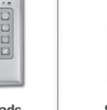
Camden CV-626 CV-634W Piezo Keypad W Wiegand Output Installation Instructions
Open the original PDF document
View PDF


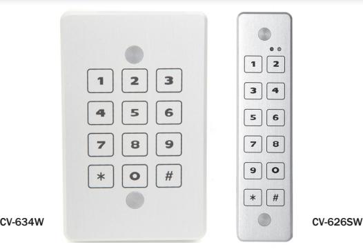
Model CV-626/CV-634W Piezo Keypad W/ Wiegand Output Installation Instruction
Protocol: Wiegand 8 or 26bit with programmable Site Code
Power Supply: 12 to 24 VDC
Power Standby Consumption: 150 mA max
Mounting: Single Gang Switch Box, or directly to the wall.
Environment: IP68; 100% relative humidity Temperature: - 4° to + 158°F (- 20° to + 70°C) CLICK-N-LOCK mounting screw protection.
| WIRING COLOR | FUNCTION | ELECTRICAL FUNCTION |
|---|---|---|
| RED | Input Voltage | 12 - 24 VDC |
| BLACK | Ground | |
| GREEN | Data 0 | Open collector 2.2K ohm pull-up to internal +5V |
| WHITE | Data 1 | Open collector 2.2K ohm pull-up to internal +5V |
| BROWN | LED Control | "LOW" = Green LED |
| BLUE | LED Control | Red LED constant unless Brown wire is "LOW" |
| BROWN + BLUE | LED Control | "LOW" = Yellow LED |
| GREY | BUZZER Input | "LOW" Activate Buzzer |
| VIOLET | CCTV Output | Open collector 0.2 A activated with each key for 30 Sec. |
| YELLOW | Tamper Output | Open collector 0.200 A "Low" when light sensed |
| PINK | HOLD Input |
"LOW" data is stored in Buffer, "HIGH" buffered
data is sent |
Keypad Protocols
8 Bit Specifications:
| KEY | OUTPUT | KEY | OUTPUT |
|---|---|---|---|
| 0 | 11110000 | 6 | 10010110 |
| 1 | 11100001 | 7 | 10000111 |
| 2 | 11010010 | 8 | 01111000 |
| 3 | 11000011 | 9 | 01101001 |
| 4 | 10110100 | * | 01011010 |
| 5 | 10100101 | # | 01001011 |
26 Bit Wiegand Specification
The following WIEGAND output is sent each time the # (enter) key is pressed.
| P | SSSSSSSS | NNNNNNNNNNNNNNN | P | |||
|---|---|---|---|---|---|---|
| BIT | 1 | 2 | 9 | 10 | 25 | 26 |
- BIT 1 is an even parity for the following 12 bits. The sum of bits 1-13 is even.
- BITS 2-9 are the programmable SITE CODE (from 000 to 255).
- BITS 10 25 this is the number entered prior to pressing # (enter). Leading 0's are added as required. Bit 10 is most significant.
- BIT 26 is an odd parity over the previous 12 bits. The sum of bits 14-26 is odd.
EXAMPLE:
A code of 123 is entered: 1 00000100 0000000001111011 1 (site code 004)
The data is sent at 2 msec per bit with a pulse duration of 70 usec.
An error code is generated by any of the following:
Wiegand 26 bit – Pressing 65,535 or any number above 65 535. An error Code will send all binary 1's to your panel and the red LED will blink. Do NOT program your panel to accept code number 65 535.
LED Configuration
The CV-634W keypad has the ability to be used with either one or two wire LED controller output. Depending on your system type, please determine the prope wiring using the procedure below.
One Wire Mode
- 1. Configure using the BROWN wire (default)
- 2. In this mode the Red LED will be on until a valid PIN is entered.
- 3. When a valid PIN is entered, the BROWN wire will be pulled "LOW" and the Green LED will illuminate.
Two Wire Mode
- 1. Configure using the BROWN wire for the Green LED and the Blue wire for the Red LED.
- 2. Depending on the panel type, when the BLUE wire is pulled "LOW" the Red LED will be illuminated.
- 3. After a valid PIN is entered, the BROWN wire will be pulled "LOW" illuminating the Green LED.
- 4. If both BROWN and BLUE wires are pulled low, the LED will go to Yellow.
Installation
Surface/Single Gang/Mullion Mount
- 1. Verify mounting location and using supplied template pre drill mounting holes and wiring harness.
- 2. Wire the unknit as per wiring chart. Do not attach the keypad to the wall until you fully configure and test its operation.
- 3. Power on the system and configure the keypad to match system requirements.
- 4. Once configured and tested, mount the keypad using the supplied screws and insert the anti-vandal covers.
- 5. Retest the operation and place unit into service.
Configuring the Keypad
The keypad has 4 options to configure the output to match your system requirements. Once wired and the voltage is applied, you can configure the keypad at any time.
Setting the Master Code
1. Enter 99 1-2-3-4 99 The keypad enters programming
mode, the Green LED blinks.
2. Enter 1 The Red LED blinks for 3 seconds
3. Enter new code
99 x-x-x-x 99 This is the new Master Code, keep
a record of this number
4. Green LED on for 3 seconds and the buzzer will beep.
Setting the Keypad Output Protocol
- 1. For 26 bit Wiegand, Please know your site code prior to configuring.
- 2. Enter 99 master code 99 The keypad enters programming
mode, the Green LED blinks
3. Enter 2 The Red LED blinks for 3 seconds
4. Enter 8 99 for 8 bit protocol
Enter 26 x-x-x 99 for 26 bit protocol (x-x-x is the Site
Code, from 000 – 255)
5. Green LED is on for 3 seconds and the buzzer will beep twice.
NOTES:
- 1. Wiegand keypads are programmed with default Wiegand 26 bit site code 000.
- 2. The keypads are programmed with default Master Code 99 1234 99
- 3. In normal mode condition, Red LED is constantly ON.
- 4. Each key will activate the buzzer and the Yellow LED.
5502 Timberlea Blvd., Mississauga, ON Canada L4W 2T7
www.camdencontrols.com Toll Free: 1.877.226.3369
File: CV-634W Instructions.indd- Rev2
Revised: 17/05/2017 Part No: 40-82B057