Camden CV-601 MProx Installation Instructions
Open the original PDF document
View PDF


CV-601 MProx Installation Instructions
Package Contents
- (1) Programming Controller
- (1) Proximity Card Reader with plug-in cable
- Hardware package with controller mounting bracket and screws
- (2) 47V rated varistors (MOV)
GENERAL DESCRIPTION
Camden CV-601 is an access control system for one door.
The controller has an input for a proximity card reader (included as part of the system), a 5 amp relay to activate an electric lock and memory for up to 999 users.
The controller has 4 programming buttons and a 3-digit display for:
- 1. Programming new cards/fobs into the memory (individually or by batch enrolling).
- 2. Deleting cards/fobs from the memory (individually, by sets, or all).
- 3. Selecting either Maintained (latching) or Timed Operation mode, (and adjusting time delay).
- 4. Setting a User Password to protect programming operations.
The controller is supplied in a plastic enclosure suitable for indoor installation and for mounting on supplied rails. The proximity card reader is door jamb width, and is designed for indoor or outdoor applications.
FUNCTIONS
1. Programming new credentials (cards or fobs) into the system
Cards or fobs are enrolled into individual memory slots, numbered 1-999. In order to enroll a card/fob, the
memory slot must be "free" (non-assigned). When programming the system, be sure to keep a record (excel spreadsheet or paper record) of who has been enrolled, and to which memory slot they were assigned. Should that person lose their card/fob, or you wish to cancel that person's access privileges, it is essential that you have a record of which memory slot they were assigned.
1.1 Individual enrollment of cards or fobs
- a) Press the RED and BLUE buttons simultaneously
- b) Select a free (non-assigned) storage location. Hit the red button to scroll up, or the blue button to scroll down. Assigned locations will have decimals points between the displayed numbers. Non-assigned (free) locations are indicated by decimals points being off.
- c) Once you have found a free slot, present the badge to be enrolled (card of fob) to the proximity reader (decimal points will go on).
- d) Confirm your selection by pressing the GREEN button (decimal points will briefly flash).
- e) Repeat steps b-d to enter other credentials or simultaneously press RED and BLUE buttons to exit from programming mode.
1.2 Batch loading of cards or fobs
Cards/fobs may be quickly enrolled in the system in "batches", rather than on a "one by one" basis.
The credentials to be enrolled must be sequentially numbered in order to do so.
- a) Press the RED and BLUE buttons simultaneously to access the programming mode.
- b) Press the YELLOW button to access the Function selection menu.
- c) Select Function F03 by pressing the red button twice.
- d) Confirm this selection by pressing the GREEN button.
Batch loading of cards or fobs (Cont'd.)
e) The start memory location will now appear, default being the first available number. A decimal point to left will appear indicating that the initial memory location is being selected. Select the desired "start" location by scrolling up or down on the RED or BLUE buttons.
For a new system, the initial memory location is typically 001 . However, if 20 cards had previously been enrolled in slots 001-020, your new "start" location should be 021 .
NOTE: If you accept 001 as the start location, you will overwrite the existing cards/fobs.
- f) Press the GREEN button to confirm the start memory location.
- g) Now select the final memory location by pressing the RED button to scroll up until the desired location is reached. A decimal point to the right will now appear indicating that the final location is being selected.
- h) Confirm selection of the final memory location by pressing the GREEN button. The system is now ready to "load".
- i) Present the initial card in the sequence. The system will now automatically "load" the sequenced cards into the system.
Example: Start memory location = 120, final memory location = 127. By presenting card #112233 to the reader, 8 cards will be entered in memory slots #120- 127. The numbers enrolled will be 112233-112240
- j) Press the GREEN button to confirm programming.
- k) Press the RED & BLUE buttons to exit from the Programming Mode.
| Location | Card |
|---|---|
| 120 | 112233 |
| 121 | 112234 |
| 122 | 112235 |
| 123 | 112236 |
| 124 | 112237 |
| 125 | 112238 |
| 126 | 112239 |
| 127 | 112240 |
2. Deleting Cards or Fobs
2.1 Deleting Individual Cards or Fobs
- a) Press the RED and BLUE buttons simultaneously to access the programming mode.
- b) Select the storage location to be deleted by scrolling up or down with the RED or BLUE buttons. If decimal points are on, this indicates that the location has a card/fob programmed into it.
- c) Press the GREEN button. The letter -C- (cancel) will now appear on the left-hand side of the display.
- d) Press the GREEN button again to confirm deletion. The decimal points will go off and the storage location is now freed up, and the card/fob that was programmed to that location will no longer work.
- e) Repeat steps b-d to delete other codes.
- f) Press the RED & BLUE buttons to exit from the Programming Mode.
2.2 Deleting a set of Cards or Fobs
- a) Press the RED and BLUE buttons simultaneously to access the programming mode.
- b) Press the YELLOW button to access the Function selection menu.
- c) Select Function F04 by pressing the red button 3 times.
- d) Confirm your selection by pressing the GREEN button.
- e) Select the first location to be deleted by scrolling up or down with the RED or BLUE buttons.
- f) Press the GREEN button to confirm the first location to be deleted.
- g) Select the last location to be deleted by scrolling up with the red button.
- h) Press the GREEN button to confirm the last location to be deleted. The letter C will appear on the left hand side of the display.
- i) Press the GREEN button again and the system will automatically delete the range selected.
- j) Press the RED & BLUE buttons to exit from the Programming Mode.
2.3 Deleting all Cards or Fobs
a) Press the RED and BLUE buttons simultaneously to access the programming mode.
Deleting all Cards or Fobs (Cont'd.)
- b) Press the YELLOW button to access the function selection menu
- c) Press the RED button to scroll to Function F05
- d) Press the GREEN button to confirm your selection. The letter C will appear on the left side of the display.
- e) Press the GREEN button again, to confirm that you wish to delete all codes. The CV-600 will now fully delete all of the stored codes. All other stored parameters (relay times, password, etc.)
- f) Press the RED & BLUE buttons to exit from the Programming Mode.
3. Selecting Relay operating mode and relay timing
- a) Press the RED and BLUE buttons simultaneously to access the programming mode.
- b) Press the YELLOW button to access the function selection menu.
- c) Press the GREEN key to confirm your selection F01 . The existing setting will appear on the display. If 000 is displayed, the relay will operate in the maintained (latching) mode. If a number between 1-180 is displayed, the relay will activate for this number of seconds. Push the red button to scroll up, or the blue button to scroll down to the desire setting.
- d) Press the GREEN button to confirm this selection. The display will return to the function mode and the new setting will be stored.
- e) Press the RED and BLUE keys simultaneously to exit from the programming mode.
4. Setting up the password function (optional)
Please read this section completely before adding password. By enabling/setting up this function, only those with the valid password will be able to program the system. Passwords may be easily deleted (see section 4.2 below). The system will accept only one password- programming a second password will void out the first password entered.
NOTE: if the password is lost or forgotten, contact the factory on how to reset the system (all system settings and programmed information will be lost!!!)
4.1 Adding a password
a) Press the RED and BLUE buttons simultaneously to access the programming mode.
- b) Press the YELLOW button to access the Function selection menu.
- c) Press the RED button once to scroll to Function F02 .
- d) Confirm this selection by pressing the GREEN button. The letter P (password) will appear on the left side of the display.
- e) Select a "password" by pressing six times on any combination of the colored buttons.
For example: red, red, green, green, blue, blue. Each time a button is pressed, the letter P will flash.
IMPORTANT: Be sure to write down/remember the sequence, as there is no way to retrieve this password from the system. A complete system reset will be required if the sequence cannot be recalled!!!
Once the sequence is completed, the function selection menu will reappear on the display.
Failure to complete the sequence within 10 seconds will abort the password entry. The password is stored in EEPROM and is requested whenever RED & BLUE are pressed to access the programming mode. The letter P will appear on the left side of the display. Enter the sequence of six colored buttons that correspond to the password. Each time a button is pressed, the letter P will flash. Once the correct 6 color password is entered, the programming mode can be accessed. If the sequence entered is incorrect, the displays will go off. This also avoids entry of incorrect passwords or erroneous pressing of any key.
To retry, press the RED & BLUE buttons again.
4.2 Deleting an existing password
-
a) Press the RED and BLUE buttons simultaneously to access the programming mode.
- b) Enter the password to be deleted by pressing the correct sequence of colored buttons.
- c) Press the YELLOW key to access the function selection menu.
- d) Press the RED button once to scroll to Function F02 .
- e) Confirm this selection by pressing the GREEN button.
- f) Allow time-out (10 seconds) to elapse; password is deleted and will not be requested upon any subsequent accessing of programming mode.
IMPORTANT: DO NOT press any buttons for 10 seconds, or a new password will be created.
Deleting an existing password (Cont'd.)
- Should you wish to program a new password, see section 4.1 above.
- g) Press the RED & BLUE buttons to exit from the Programming Mode.
5. Using the Shorting Jumper (optional)
This function allows you to add an external device in the circuit for applications where 2 (dual) contact closures are required. Examples of this type of switch would be a Loop detector, keypad, key switch, or Time clock.
To enable this function, remove the supplied shorting jumper from Terminals 5 & 7 (see diagram below) and replace with your external N/O momentary switch. (Since these terminals are in fact connected directly in series with the output relay, a connection (shorting jumper or your device) is required for the circuit to be made.)
Diagram of terminal blocks and keys:
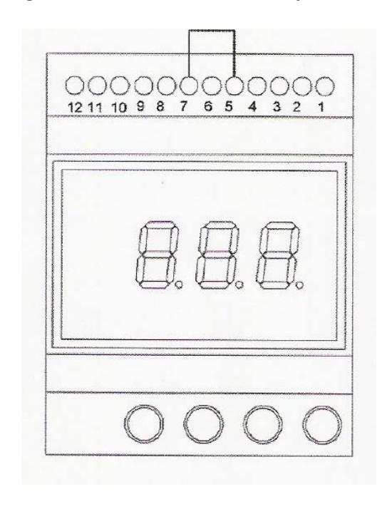
TERMINAL BLOCK
| 1. Not Used | |
|---|---|
| 2.Relay contact: N.C | |
| 3. Relay contact: common | |
| 4. Relay contact: N.O | |
| 5. Relay enabling | |
| 6. Relay forced activation | |
| 7. GROUND | Black |
| 8. Wiegand data input (DATA 1) | White |
| 9. Wiegand data input (DATA 0) | Green |
| 10. Output for reader power supply (9Vdc) | Red |
| 11. Power supply (12V AC/DC) | |
| 12. Power supply (12V AC/DC) |
Technical Specifications:
Power supply 12V AC/DC
Inputs 1 data input with Wiegand
protocol
Memory capacity 999 users
Relay Output 1 form C contact
Request to exit input Inside push button input
(normally open momentary)
Relay operating mode Timed from 1 to 180 seconds or
maintained (latching)
Relay contact capacity 5 amps @ 125 VAC or 30 VDC Programming 4 buttons (YELLOW, RED, BLUE,
GREEN) and 3 digit display
Dimensions
Controller 2 ¾" W X 3 ½" H X 2 ¼"D
(70 x 90 x 60mm)
Reader 1 ¾" W x 4 ½" H x ¾" D
(45 x 114 x 18mm)