Camden CV-550SPK V2 Waterproof Keypad ReaderController Installation Instructions
Open the original PDF document
View PDF


Packing List
| NAME | MODEL/SIZE | QTY |
|---|---|---|
| Self tapping screw |
0.15" x 1.06"
(4mm × 27 mm) |
2 |
| Rubber plug |
0.23" x 1.2"
(6mm × 30 mm) |
2 |
| Star screw driver |
0.78" x 2.4"
(20mm × 60mm) |
1 |
| Two-electrode valve | 1N4007 | 1 |
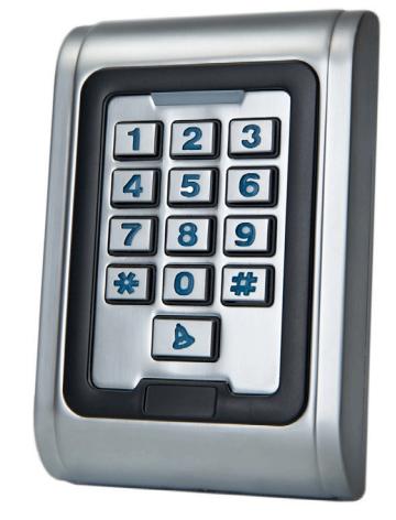
1. Description
The CV-550SPK is a single door multifunction standalone access control keypad with a Wiegand input/output interface. It is suitable for mounting either indoors or outdoors in harsh environments. It is housed in a strong, sturdy and vandal proof Zinc Alloy electroplated case. The electronics are fully potted so the CV-550SPK is waterproof and conforms to IP68.
The CV-550SPK supports up to 2000 users in either a Card, 4~6 digit PIN, or a Card + PIN option. The built-in card reader supports 125KHZ HID 26, 34 or 37 bit cards/ tags. The CV-550SPK has many extra features including block enrollment, Wiegand 26 bit interface, and backlit keypad.
These features make CV-550SPK an ideal choice for door access for commercial and industrial applications such as factories, offices, warehouses, laboratories, banks and prisons.
2. Features
- Waterproof, conforms to IP68
- Strong Zinc Alloy Electroplated anti-vandal case
- Full programming from the keypad
- 2,000 users, supports Card, PIN, Card + PIN
- Can be used as a stand alone keypad, Pin length 4~6 digits
- Backlit keypad
- Wiegand input & output
- One programmable Relay output, NO, NC, COM
- Adjustable Door Output time, Alarm time, Door Open time
- Block enrollment, can enroll maximum 2000 consecutive cards within 2 minutes
- Very low power consumption (< 60mA)
- Easy to install and program
- Built in light dependent resistor (LDR) for anti-tamper
- Built in buzzer
- Red, Yellow and Green LEDs display the working status
- 12 VDC +/- 10%.
- Three-year warranty
3. Specifications
| Input voltage | 12 VDC +/- 10% |
| IP rating | 68 |
| Idle current | 25mA |
| Contact type | (1) Form 'C' |
| Contact rating | 1 Amp@30VDC |
| Alarm output load | 1 Amp@30VDC |
| Ring bell load | 1 Amp@30VDC |
| Card read distance | 1.75" (40Mm) Max |
| Card frequency | 125KHz, EM and HID |
| Card format | 26, 34 and 37 bit Wiegand |
| Keypad format | 4bit, 8 bit and Virtual card number |
| Operating | -49°F to 113°F |
| temperature | (-45°C to 55°C) |
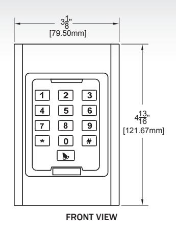
| Dimensions | 4 13/16"H x 3 1/8" W x 1 1/16" |
| 121.67mm x 79.50 mm x 26.42mm |
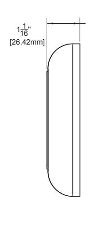
SIDE VIEW
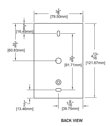
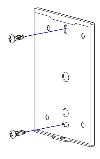
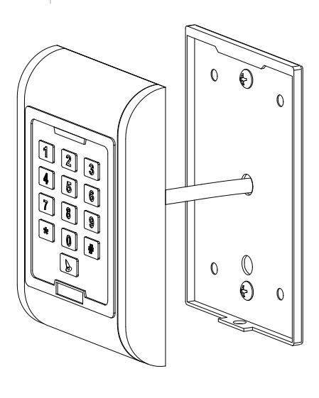
4. Installation
- Remove the back cover from the keypad using the supplied special screw driver
- Drill 2 holes on the wall for the Self tapping screws and 1 hole for the cable
- Put the supplied rubber bungs to into the two holes
- Fix the back cover firmly on the wall with 4 flat head screws
- Thread the cable through the cable hole
- Attach the keypad to the back cover.
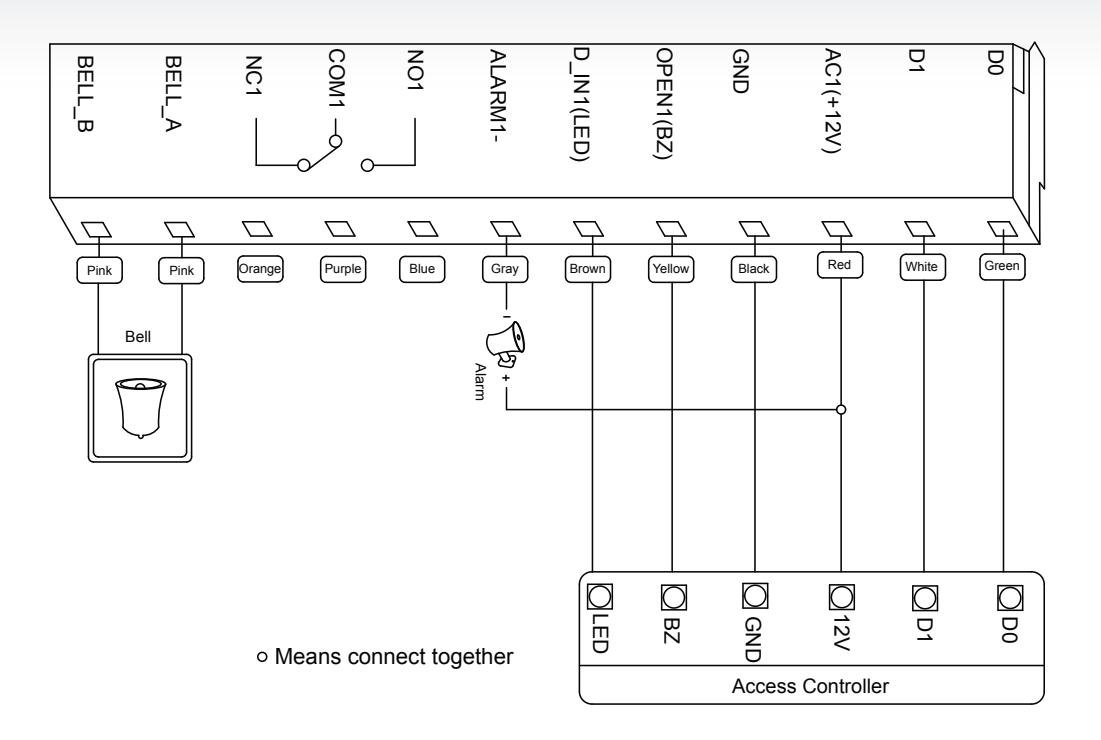
5. Wiring
| NO. | MARKS | COLOR | DESCRIPTION |
|---|---|---|---|
| 1 | BELL_A | Pink | Doorbell button |
| 2 | BELL_B | Pink | Doorbell button |
| 3 | D0 | Green | Wiegand output D0 |
| 4 | D1 | White | Wiegand output D1 |
| 5 | ALARM | Gray | Alarm |
| 6 | OPEN | Yellow | Request to Open (BUZ) |
| 7 | D_IN | Brown | Door Contact (LED) |
| 8 | DC | Red | Power IN |
| 9 | GND | Black | Ground |
| 10 | NO | Blue | Relay NO |
| 11 | COM | Purple | Relay Com |
| 12 | NC | Orange | Relay NC |
6. Sound and Light Indication
| OPERATION | LED COLOR | BUZZER |
|---|---|---|
| Standby | Red Flash | |
| Press Key | Di | |
| Read Card | Green | Di |
| Door 1 Open | Green | Di |
| Door 2 Open | Green Flash | Di |
| Operation Successful | Green | Di |
| Operation Failed | Di-Di-Di | |
| PIN Inputting | Red | |
| Card & Pin Reading | Red | |
| Multi Card Reading | Red | |
| Under Menu | Red | |
| Under Setting | Orange | |
| Manager Card Enter | Orange | Di-Di |
| Manager Card Exit | Red Flash | Di |
| Alarm | Red Quick Flash | Alarm |
7. Quick Programming Guide
7.1 Administrator Setting
| STANDBY |
MASTER
CODE |
MENU | SETTING | REMARKS | FUNCTIONS |
|---|---|---|---|---|---|
| Red Flash | Red | Red | Orange | ||
| * |
Master
Code # |
00 |
New master code# Repeat new
master code # (Note: Code length: 6-8 digits) |
Factory
default:999999 |
Change the master
code |
| 01 | Read Manager Add Card | Default |
Set Manager Add
Card |
||
| 02 | Read Manager Delete Card |
Set Manager Delete
Card |
|||
| 03 | Read Anti-duress card | Anti-duress card | |||
| 05 | Anti-duress PIN# | Anti-duress PIN | |||
| 07 | 000# | Delete All Users | |||
| 51 | Master open |
7.2 User Setting
| STANDBY |
MASTER
CODE |
MENU | SETTING | REMARKS | FUNCTIONS |
|---|---|---|---|---|---|
| Red Flash | Red | Red | Orange | ||
| * |
Master
Code # |
11 | Red card |
Users can be added
continuously without |
To add card users |
|
User ID number# read
card |
exiting programming mode | ||||
| Card number# | |||||
|
ID number# card
number# |
|||||
| User ID number# PIN# | To add PIN users | ||||
| 12 | Read card | Users can be deleted | To delete users | ||
| User ID number# | continuously without | ||||
| Card number# | exiting programming mode | ||||
| 13 | 0# | Default 2 | Entry by card | ||
| 1# | Entry by card+PIN | ||||
| 2# |
Entry by either card or
PIN |
||||
| 14 | 0-99# | Default 5 | Set door relay time | ||
| 15 | 0# | Default 0 |
Relay Setting-Pulse
mode |
||
| 1# |
Relay Setting-Toggle
mode |
||||
| 16 | 1-10# | Default 1 |
To set open door by
multi cards |
||
| 17 |
User ID number#,
card number#, card quantity # |
Card number= FC+card ID
Max FC= 255, Max ID = 65535 |
To add a series cards
users |
7.3 System Setting
| STANDBY | MASTER CODE | MENU | SETTING | REMARKS | FUNCTIONS |
|---|---|---|---|---|---|
| Red Flash | Red | Red | Orange | ||
| * | Master | 30 | 0-15# | Default 0 | To set facility code |
| Code # | 31 | 0# | This setting is not | Wiegand reader | |
| 1# | affected by resetting to | Standalone for single door | |||
| 2# | factory default. | ||||
| 3# | |||||
| 4# | |||||
| 5# | Anti-passback for single door | ||||
| 6# | |||||
| 32 |
26, 34 or
37# |
Default 26 | To set Wiegand format | ||
| 33 | 0-2# | This setting is not affected by resetting to factory default. | To set keypad transmission format 0 = 26 bit weigand 1 = 4 bit burst 2 = 8 bit burst | ||
| 34 | 1-3# | Default 1 | To set alarm time in minutes | ||
| 35 | 35 | 0# | Default 0 | Normal mode | |
| 1# | Lock out mode | ||||
| 2# | Alarm mode |
7.4 User Optional Setting
| STANDBY |
MASTER
CODE |
MENU | SETTING | REMARKS | FUNCTIONS |
|---|---|---|---|---|---|
| Red Flash | Red | Red | Orange | ||
| * |
Master
Code # |
41 | 0# | Buzzer is turned off, except while in programming mode | |
| 1# | Default 1 | Buzzer will sound during key presses | |||
| 42 | 0# | Disable keypad backlighting | |||
| 1# | Enable keypad backlighting | ||||
| 2# | Default 2 | Automatic mode, normally it is off (stand-by mode) but will illuminate when the key is pressed | |||
| 43 | 0# | LED Light Disable while in stand-by | |||
| 1# | Default 1 | LED flashes while in stand-by |
Notes:
- 1. Master code must be 6-8 digits.
- 2. Anti-duress PIN must be 8 digits.
- 3. User PIN is 4-6 digits.
- 4. The user ID number is any number from 1-2000.
- 5. Card number must be 8 or 10 digits, if the card number is less than 8 or 10 digits, enter 0 before the card number.
- 6. Door open time is 0-99 second, 0=50mS.
- 7. While operating the keypad, pressing # means to confirm the input digits, in operation of a cycle adding or deleting cards, pressing # means to end the cycle operation and back up the operation; pressing * means to exit the operation.
- 8. When block enrolling cards, the facility code and the card ID are entered as one number. The facility code is from 1 – 255 and the card ID is from 0-65,535. For example, if our facility code is 45 and your card ID is 56987, you would enter 04556987 as your first card number. The system will automatically increment the card ID by 1 for every entry until the total number of cards in the block are entered. The maximum number of cards to block enroll is 2,000.
- 9. Keypad/Reader Wiegand modes are set at the factory to 26 bit. If the output format is changed through programming, the changes are not affected by a reset to factory defaults.
8. Administrator Setting
| 8.1 ADMINISTRATOR SETTING | |||
|---|---|---|---|
| Administrator setting on keypad | Press * Master code # factory default:999999 | ||
| Change the master code | Press 00 new code # repeat new master code# | ||
| Note: Master Code length: 6~8 digits | |||
| 8.2 SET MANAGER CARD | |||
| Set manager add card | Press 01 read manager add card | ||
| Set manager delete card | Press 02 read manager delete card | ||
|
Note: When adding the new manager card, the new one will automatically cover the old card, only one manager
card for one device. |
|||
| 8.3 SET ANTI-DURESS CARD | |||
| Set anti-duress card for Zone 1 | Press 03 read anti-duress card (Zone 1) | ||
| Set anti-duress card for Zone 2 (not available) | Press 04 read anti-duress card (Zone 2) | ||
|
Note: When adding the new anti-duress card, the new one will automatically replace the old card, only one anti
duress card per one device. |
|||
| 8.4 SET ANTI-DURESS PIN | |||
| Set anti-duress PIN | Press 05 8-digit duress PIN# (Zone 1) | ||
| 8.5 DELETE ALL USERS | |||
| Delete all users | Press 07 0000 # | ||
| 8.6 ACTIVATE THE LOCK OUTPUT WHILE IN PROGRAMMING MODE | ||||
|---|---|---|---|---|
| Activate the lock output while in programming Mode | Press * Master code # factory default: 999999, | |||
| Press 51 | ||||
| Note: The relay will operate for the relay on time. | ||||
| 8.7 USERS SETTING FOR ZONE 1 | ||||
| Read card to add user | Press 11 read card # read card# | |||
| Use ID Number and read card to add user |
Press 11 ID number # read cardID number # read
card # |
|||
| Use card number | Press 11 card number #card number## | |||
|
Note: 1. Card number must be 8 or 10 digits, if the card number is less than 8 or 10 digits, input 0 before the
card number. 2. Automatically increases, the user ID will be generated by the machine automatically, the range is 1 ~ 2000, and automatically search from 1 to 2000. |
||||
| Use ID number and card number to add user |
Press 11 ID number # 8-digit card number # ID
number # 8-digit card number ## |
|||
| Note: ID number is 1~4 digits, the range is 1~2000, 1, 01, 001, 0001, all these mean ID number 1. | ||||
| Use ID number and PIN to add user | Press 11 ID number# PIN #ID number #PIN ## | |||
| Note: The PIN is any 4-6 digits, except 1234 which is reserved. | ||||
| 8.8 DELETE USER | ||||
| Read card to delete user | Press 12 read card read card # | |||
| Use ID number to delete user | Press 12 ID number # ID number ## | |||
| Use card number to delete user | Press 12 card number # card number ## | |||
| Delete all users | Press 07 0000 # | |||
| 8.9 SET OPENING DOOR MODE | ||||
| Entry is by card only | Press 13 0 # | |||
| Entry is by card and PIN together | Press 13 1 # | |||
| Entry is by card or PIN (factory default) | Press 13 2 # | |||
| 8.10 SET DOOR RELAY TIME | ||||
| Set door relay time | Press 14 0~99 # | |||
| Note: 0~99 is to set the door delay time 0-99 seconds, factory default is 5 seconds | ||||
| 8.11 SET RELAY MODE | ||||
|---|---|---|---|---|
| Relay setting -pulse mode | Press 15 0 # | |||
| Relay setting-toggle mode | Press 15 1 # | |||
| 8.12 SET OPENING DOOR BY MULTI CARDS | ||||
| Set opening door by multi cards | Press 16 card quantity # | |||
|
Note: The door will be opened only after reading all the valid cards up to the card quantity setting. It is only for
card entry mode (Factory default setting :1) |
||||
| 8.13 ADD A SERIES CONSECUTIVE CARDS USERS | ||||
| Add a series consecutive cards users | Press 17 ID number # card number # card quantity # | |||
|
When block enrolling cards, the facility code and the card ID are entered as one number. The facility code is from
1 – 255 and the card ID is from 0-65,535. For example, if our facility code is 45 and your card ID is 56987, you would enter 04556987 as your first card number. The system will automatically increment the card ID by 1 for every entry until the total number of cards in the block are entered. The maximum number of cards to block enroll is 2,000. |
||||
| 8.14 SYSTEM SETTING | ||||
| To set facility code | Press 30 0~15 # | |||
| Note: code should be 0~15, factory default setting :0 | ||||
| Wiegand Reader | Press 31 0 # | |||
| Stand alone for single door (Factory default setting) | Press 31 1 # | |||
| 8.15 TO SET WIEGAND FORMAT | ||||
| To set Wiegand format | Press 32 26 34 37 # | |||
| Note: factory default setting: 26 | ||||
| 8.16 SETTING KEYPAD TRANSMISSION FORMAT | ||||
| Setting keypad transmission format | Press 33 0~2 # | |||
| Note: Keypad transmission format is 0 1 2, factory default is 0; not affected by resetting to factory default. | ||||
| 8.17 SETTING ALARM TIME | ||||
|
Setting alarm time
Press 34 1~3 # |
||||
| Note: Factory default is 1 minute; not affected by resetting to factory default. | ||||
| 8.18 SETTING SAFE MODE | ||||
|---|---|---|---|---|
| Normal mode (factory default) | Press 35 0 # | |||
| Lock out mode | Press 35 1 # | |||
| If an invalid card or wrong PIN is input 10 times in 10 minutes, uses will be locked out 10 minutes | ||||
| Alarm mode | Press 35 2 # | |||
| If an invalid card or wrong PIN is input 10 times in 10 minutes, external alarm and built-in buzzer will sound. | ||||
| 8.19.1 USER OPTIONAL SETTING | ||||
| Setting keypad tone OFF or ON | Press 41 0 # OFF | |||
| Press 41 1 # ON (Default) | ||||
| 8.19.2 SETTING KEYPAD BACKLIGHT | ||||
| Disable keypad backlight | Press 42 0 # | |||
| Enable keypad backlight | Press 42 1 # | |||
| Automatic mode (factory default setting) |
Press 42 2 # Keypad will illuminate when a key is
pressed |
|||
| 8.20.3 SETTING LED LIGHT (STANDBY STATUS) | ||||
| Disable LED light | Press 43 0 # | |||
| Flash LED light (factory default setting) | Press 43 1 # | |||
Manager Card Operation
8.21 Add user
- Read Manager Add Card, read user cards continuously, read Manager Add card again.
8.22 Delete user
- Read Manager Delete Card, read user cards continuously, read Manager Delete card again.
9. User Operation
9.1 Entry by card mode, set multi cards to open door when card quantity is 1
- Read user card, lock will be unlocked
- 9.2 Entry by card mode, set multi cards to open door when card quantity is 2-10
- Read these cards one by one, present each card in 5 seconds, lock will be unlocked
9.3 Entry by card and PIN
- Present card, then press PIN (4 to 6 digits ), #, lock will be unlocked
9.4 Entry by card or PIN mode
- Present card, lock will be unlocked
- Or Press PIN (4 to 6 digits), #, lock will be unlocked
9.5 Relay mode
- Relay setting -pulse mode
- Every time a valid card/tag read or PIN input, the relay will operate, for the pre-set relay pulse time.
- Relay setting-toggle mode
- Every time a valid card/tag read or PIN input, the relay changes state, which will not turn back until read card/ tag or input PIN again
9.6 Modify User PIN (no need enter programming mode)
- *, read user card, press old PIN, #, new PIN # new PIN #
- Or *, press ID number # old PIN# new PIN # new PIN #
10. Alarm Function
10.1 Anti-Tamper Alarm
- If the device is disassembled illegally, the buzzer and the external alarm will operate.
10.2 Door Contact Alarm
- When connected with door contact: if the door is opened illegally, the buzzer and the external alarm will operate.
10.3 The Anti-Duress Alarm
- Preset the anti-duress card/input 8-digit anti duress PIN and press #.
- The corresponding lock will open, at the same time, the external alarm will operate, but the device buzzer will not operate.
10.4 Remove Alarm
- Read valid user card, manager card or input master code, then alarm will be removed. The alarm will time out automatically after 1 min.
11. Multi Working Mode
There are 3 working modes with this device.
- 1. Wiegand Reader
- 2. Standalone for single door
- 3. Anti-passback for single door
The factory default is Standalone for single door (we can change the default model according to customer order). User can modify the working mode, when the device reset to factory default, the setting is still valid.
11.1 Wiegand Reader Mode
In this mode, the access control works as reader, connected with the common access controller, it has following function:
- Modify master pin
- Set facility code
- Set the card transmission format
- Set the keypad transmission format
- Set optional setting
- Anti-Tamper alarm
When LED level is low, indicator light (LED) will turn into green, after 30 seconds or LED level rising, LED will back to normal.
When BZ level is low, the buzzer will beep, after 30 seconds or BZ level rising, the buzzer will back to normal.
When it used as the reader, both card number and keypad transmits in Wiegand format, the output data are shown by the low level of DO&D1 wire:
D0: Low level means 0, green wire D1: Low level means 1, white wire
The Pulse width of low level is 100uS, bit period is 1.6mS
The digits of card number can be set to 26-37 bit, should be matched with the controller. (Factory default is 26Bit)
Keypad transmission can be set in the following 3 modes (modes can be set by user)
Model 0: Virtual Card Number
The reader will transmit the PIN data when it receives the last key (#) press after PIN code
Format: Decimal card number with 10 digits, Facility code (1st~4th digit)+PIN Code (5th-10th digit)
Facility code is any digits between 0~15, PIN code is 4~6 digits
Example: facility code: 15
PIN code: 9999
Press 9999 #, then output format will be: 0015009999
PIN code: 999999
Press 999999#, then output format will be 0015999999
Model 1: 4 Bit
The output data is provided in following format after every key is pressed:
| KEY | OUTPUT IN HEX | OUTPUT IN BINARY |
|---|---|---|
| 0 | 0 | 0000 |
| 1 | 1 | 0001 |
| 2 | 2 | 0010 |
| 3 | 3 | 0011 |
| 4 | 4 | 0100 |
| 5 | 5 | 0101 |
| 6 | 6 | 0110 |
| 7 | 7 | 0111 |
| 8 | 8 | 1000 |
| 9 | 9 | 1001 |
| * | A | 1010 |
| # | B | 1011 |
Model 2: 8 Bit
The output data is transmitted in following format after every key is pressed:
| KEY | OUTPUT IN HEX | OUTPUT IN BINARY |
|---|---|---|
| 0 | 0 | 11110000 |
| 1 | 1 | 11100001 |
| 2 | 2 | 11010010 |
| 3 | 3 | 11000011 |
| 4 | 4 | 10110100 |
| 5 | 5 | 10100101 |
| 6 | 6 | 10010110 |
| 7 | 7 | 10000111 |
| 8 | 8 | 01111000 |
| 9 | 9 | 01101001 |
| * | A | 01011010 |
| # | B | 01001011 |
11.2 Stand alone for single door
In this mode, the device supports connecting external card reader for exiting door. The users of Zone 1 or external can open the door by valid card of PIN.
11.3 Anti-passback for single door
In this mode, this unit install outside is for entering door, external reader inside for exiting door, the users can only enter door when read valid card on the machine, and exit
from the inside external reader. If without the entering record from the machine, the users can not exit from the inside reader, also the Users can't enter in twice without the first exit record.
Remark: this is only for card users of Zone 1,PIN users of Zone 1 an all users of Zone 1 are invalid.
12. Diagrams for Working Modes
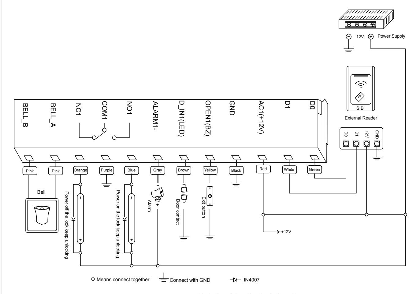
DC12V common power Mode Standalone for single door diagram Mode Anti-passback for single door diagram
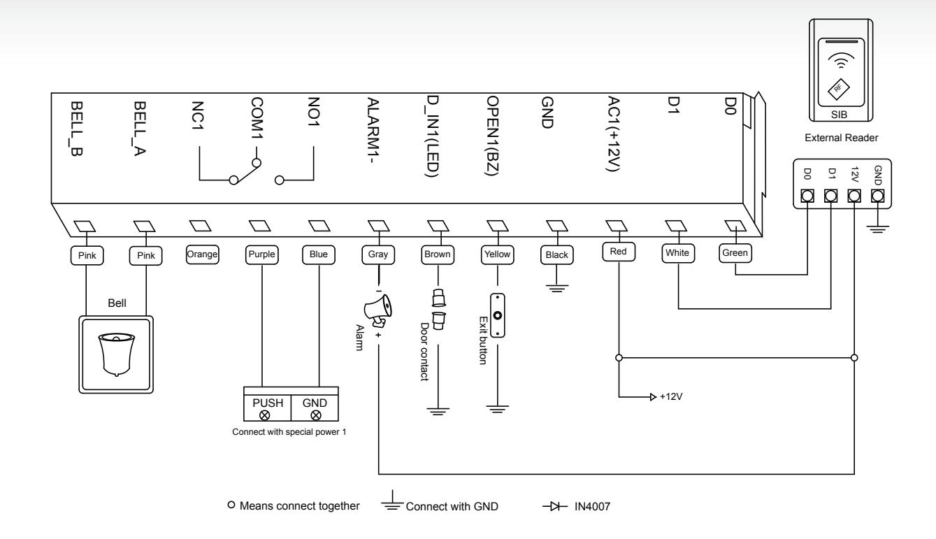
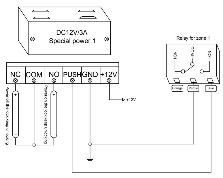
special power with lock 1 diagram
DC12V special power Mode Standalone for single door diagram Mode Anti-passback for single door diagram
Mode Wiegand reader diagram
13 Example Operations
13.1 Modify master code as 201200
press * 999999 # 0 0 201100 # 201100 #
13.2 Set Anti-duress PIN of Zone 1 as 12012000
press * 201100 # 0 5 12012000 #
13.3 Add last 8 digit card number as 00967865 and 86998736 user of Zone 1
press * 201100 # 1 1 00967865 # 86998736 #
13.4 Add first 10 digit card number as 0098786500 and 8699873600 user of Zone 2 (not available)
press * 201100 # 2 1 0098786500 # 8699873600 #
13.5 Add ID user 006, PIN 201200, Zone 2 user (not available)
press * 201100 # 2 1 6 # 201200 #
13.6 Set open mode of Zone 1 as card+PIN
press * 201100 # 1 3 1 #
13.7 Rapid increase consecutive numbers 1000 cards (start with 00987865 ID is 005)
press * 201100 # 1 7 05 # 00987865 # 1000 #
13.8 Set working mode as reader mode
press * 201100 # 3 1 0 #
13.9 Set card output format as WG34
press * 201100 # 3 2 34 #
13.10 Set master open lock 1
press * 201100 # 5 1
14. Simple Troubleshooting
| CODE | FAULT | FAULT CAUSE | SOLUTIONS |
|---|---|---|---|
| 1 | Close Read range | Quality of card | Use original card |
| 2 |
Problem in PIN
setting |
1. PIN is not standard
2. Set Password at reader mode |
1. PIN shouldn't be 1234
2. PIN is 4 to 6 digits 3. Don't set PIN at reader mode |
| 3 |
PIN can't open
door |
1 use PIN 1234
2 entry mode setting |
1. 1234 is original PIN, can't open the door,
should be modified as other PIN 2. Set open mode as entry by card or PIN. |
| 4 |
Alarms at normal
condition |
While installation, light leak
under bottom |
While installation, device should closed to
the wall |
| 5 | |||
| 6 |
No responds after
card reading |
Units are not in ready mode |
Press * key, light flash, units back to ready
mode |
| 7 |
Keypad light is not
bright |
Mode of keypad light setting
is wrong |
1. Set keypad light as shine or auto
2. Under auto mode, light shine after press keypad, delay 30 seconds |
| 8 |
Can't enter
master mode |
Forget master code |
Reset to Factory Default, master code will be
999999, only installer data is restored, user data will not be affected |
15. To Reset to Factory Default
- a. Disconnect power from the unit
- b. Press and hold # key whilst powering the unit back up
- c. On hearing two "Di" release # key, system is now back factory settings
Please note only installer data is restored, user data will not be affected.


Push Buttons Keypads Strikes Magnetic Locks Key Switches Relays & Timers Access Control

5502 Timberlea Blvd., Mississauga, ON Canada L4W 2T7
www.camdencontrols.com Toll Free: 1.877.226.3369
File: CV-550SPK Designer Series Installation Instructions.indd R4
Revision: 14/01/2019 Part No.: 40-82B223