Camden CM-AF142SO Single Gang Multi-color Dome Light with Sounder Installation Instructions
Open the original PDF document
View PDF

Door Activation Devices
CM-AF142SO
Single Gang Multi-color Dome Light, with Sounder
INSTALLATION INSTRUCTIONS
THIS PACKAGE INCLUDES
(1) Foam Gasket
(1) Lens
(1) O Ring
(1) 2-28 x 5/16"
(1) Set of Labels
Phillips locking screw
(1) LED Base
(2) Concrete wall plugs
(2) #6 x 3/4" self-tapping screws
(2) 6-32 x 3/4" screws
(4) Wire nuts
(2) 3/16" drywall plugs

1. DESCRIPTION
Camden CM-AF142SO Multi-color Dome Light, provides both visual and audible annunciation. It mounts to a standard single gang electrical box. The Superbright LED's along with the wedged shaped lamp cover provides visible illumination from either end of a corridor. The integrated piezo buzzer with adjustable volume provides up to 93 dB at 1 metre (3 feet).
2. SPECIFICATIONS
| Voltage | 12/24V AC/DC |
|---|---|
| Illumination | Superbright LED's |
| Sounder | Piezo, 93 dB max. @ 1 metre (3 ft.) |
| Current Rating |
70 mA Max for one color wire.
Combining more than one color wire = 130 mA. |
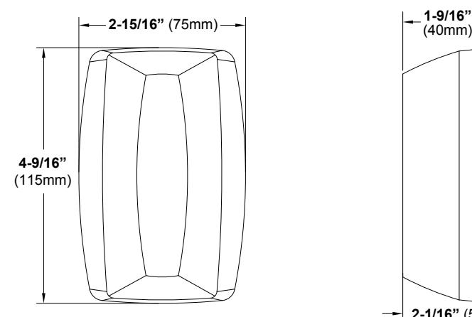
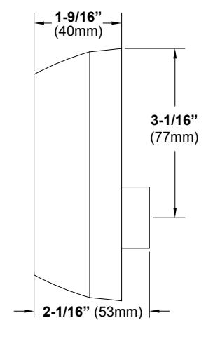
| Dimensions (Body) |
4 9/16" H x 2 15/16" W
(115mm x 75mm) |
3. SOUND VOLUME ADJUST
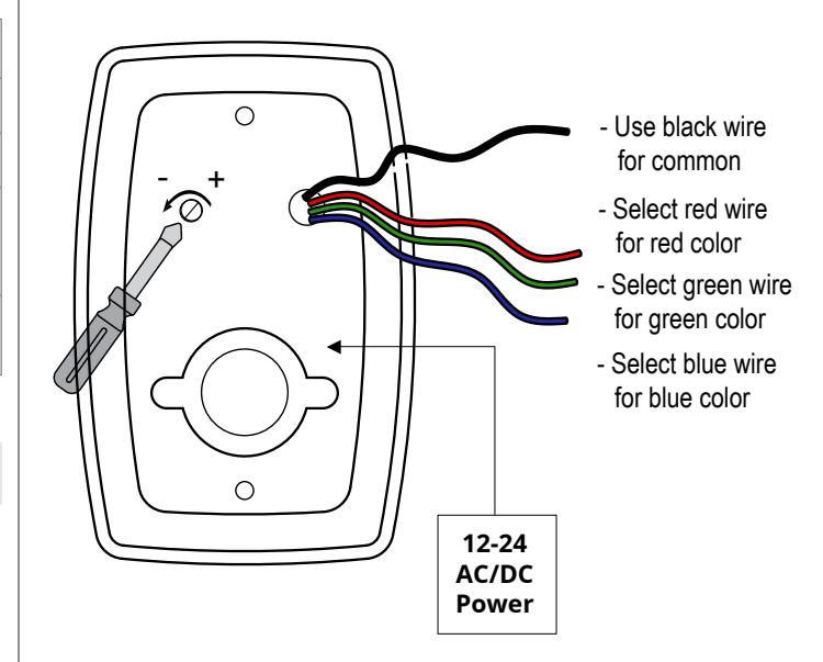
Using a small Phillips screwdriver, gently turn the volume adjustment counter clock wise to reduce the volume and clockwise to increase the volume.
4. WIRING
Camden CM-AF142SO Multi-color Dome Light is easily wired using the two of the four color coded wires supplied; Black (BLK), Red (RED), Green (GRN) and Blue (BLU). Using the BLK wire as common, selecting one of the three color wires to complete the circuit will determine the color of the Dome light. The black wire lead and any one of the color coded wires can be connected to either an AC or DC power source supplying 12 or 24 volts.
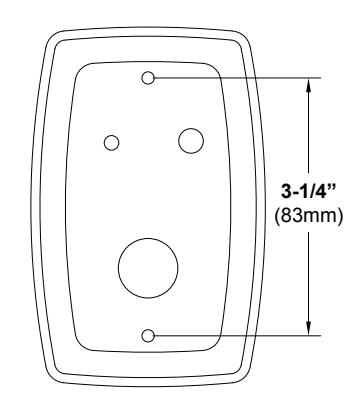
5. INSTALLATION
CM-AF142SO mounts to a standard single gang electrical box.
FLASH RATE: Increase or decrease the flash rate by gently turning the potentiometer with a small screwdriver.
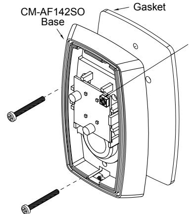
Step 1
Place the gasket (supplied) between the base unit and the electrical box. Use the 6-32 screws to fasten the base to the electrical box.
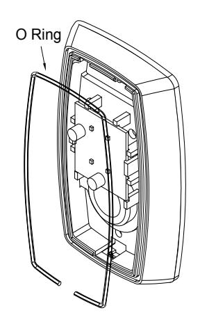
Step 2
Insert the O ring gasket into the small channel in front of the base. The O Ring does not completely close around the base. You must leave a small opening at the bottom of the base.
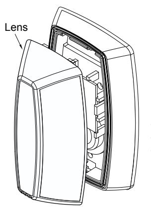
Step 3 Install the lens by inserting the large bottom tab first. The top tabs will snap in place with little effort.
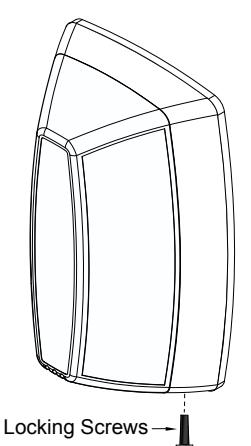
Step 4 Install the Phillips locking screw into the bottom of the base.
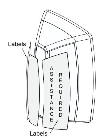
Step 5 Apply the labels as required to the lens.

Call: 1.877.226.3369 / 905.366.3377 Visit: www.camdencontrols.com
File: CM-AF142SO-Manual-R2.indd Revision: 04/07/2019 Part No.: 40-82B228