Camden CM-9000 Series Vandal Resistant Push Exit Switch Installation Instructions
Open the original PDF document
View PDF

Door Activation Devices
CM-9000 Series Vandal Resistant Push/Exit Switch
INSTALLATION INSTRUCTIONS
THIS PACKAGE INCLUDES:
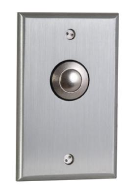
- 1- Heavy Duty 1/4" Thick Aluminum Faceplate with Vandal Resistant Switch
- 2- 6-32 x 3/4" Snake Eye Tamper Proof Screws
- 2- 6-32 x 3/4" Flat Head Phillips Screws
- 1- Key for Tamper Proof Screws (Snake Eye)
1. GENERAL DESCRIPTION
Camden Heavy-Duty CM-9000 & CM-9100 series are all-steel construction, low profile and can withstand attack of all types. The switch may be supplied with either momentary or maintained (alternating on/off) DPDT contacts.
2. SPECIFICATIONS
| Contact Rating | 6 Amps @ 12/24 VDC |
|---|---|
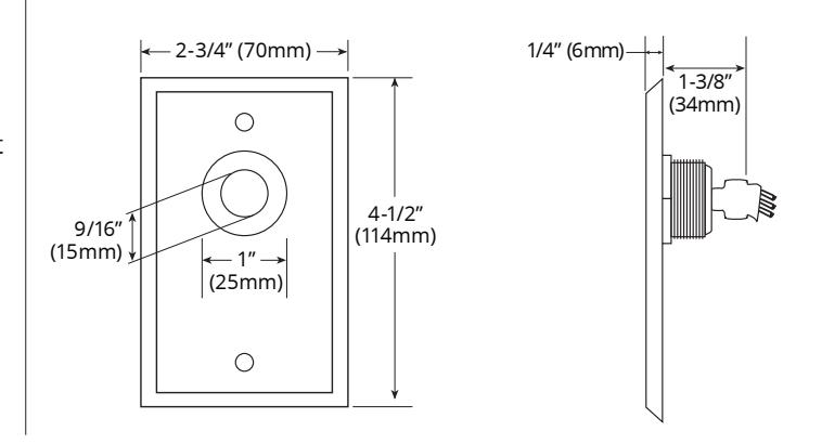
| Dimensions |
2-3/4"W x 4-1/2"H x 1-3/8"D
(70mm x 114mm x 34mm) |
- 1. Contacts are rated 6 amps @ 12/24 VDC in conformance with UL 294 standard for access control systems.
- 2. Contacts are rated 6 amps @ 120 VAC in non-UL applications, i.e. when controlling automatic doors.
3. INSTALLATION
Mounting
- 1. The switch comes already assembled to the faceplate. Only the wiring needs to be done (see next section).
- 2. Once the electrical connections are completed, attach the unit to the switch box, wall, or receptacle box using the supplied tamper proof, or stainless steel Phillips screws. For outdoor use, place the rubber weatherproofing gasket (extra-cost option) behind the faceplate prior to securing to the back box or wall.
Wiring
This switch comes in two layouts: Momentary & Maintained. Each is described as follows.
Momentary
When the button is pushed in the normally open contacts will close and when released will return to a normally open circuit.
When the button is pushed in the normally closed contacts will open and when released will return to a normally closed circuit.
Leads are color-coded as follows:
Normally open (N.O.) Blue (or Green)
Normally closed (N.C.) Orange
Common Grey (or Black)
Maintained
Using the Grey wire as the common, you will now have a closed contact across one orange wire and an open contact across the other orange wire. When the button is pushed in it will stay (latched) in the opposite state.
This means that the orange wire that was a closed contact will now stay in the open state and the other orange wire that was an open contact will now stay in the closed state until the button is pressed and released a second time returning them back to their original states.
Leads are color-coded as follows: