Camden CM-55i Flush Mount Illuminated Enclosure Installation Instructions
Open the original PDF document
View PDF


Aura™ CM-55i Flush Mount Illuminated Enclosure
Installation Instructions
| PACKAGE CONTENTS | ||||
|---|---|---|---|---|
|
CM-55i
Blue/Green/Red Aura PCB |
||||
| Dry wall Bracket | ||||
| 8-32 x 1 1/2" Screws | ||||
| #6 x 3/8" Screws | ||||
Section 1
General Description
Camden Aura™, Model CM-55i provide the Industry's 1st "Changing State" illuminated switch enclosures.
They offer field selectable blue/green/red illumination, activated directly by the switch or remotely by a relay* such as our CX-33 or EMF-2, a time-clock or access control system.
User selectable features include a 3 Amp Form C relay, and piezo speaker for audible annunciation, as well as control over the idle and active LED colours.
Another exclusive is the ability to plug in a TX-9 RF transmitter, thereby requiring only 2 conductors be run for power (& no batteries required) !!
The box is made of impact and flame resistant black ABS, and compatible with any Camden CM-41, CM-45, or CM-46 series switch.
The illumination is provided by an array of super-bright and energy efficient LED's, which can be powered by 12 or 24 volts AC/DC.
Section 2
Setup
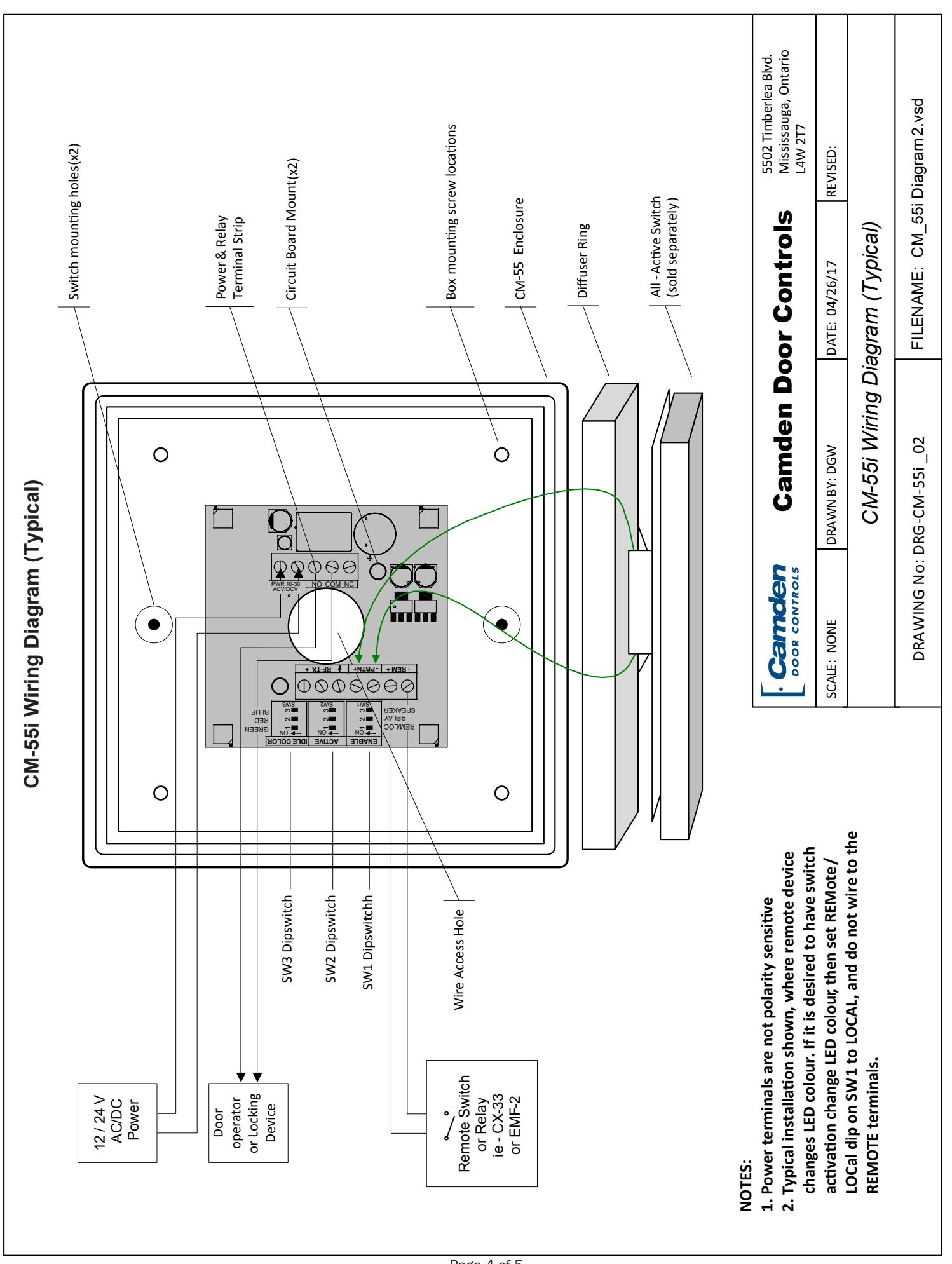
Switch SW1 contains a bank of 3 dipswitches.
Dipswitch # 3 turns the speaker on or off. Dipswitch # 2 toggles operation of the relay, and # 1 allows you to choose whether the colour will be changed locally via the push switch, or remotely.
*Note: The CX-22 Washroom relay may be used with the Aura™, however an isolating relay must be wired in parallel with the lock, and the relay's dry contact output wired into the CM-55i .
Setup
| Switch | Position | Description |
|---|---|---|
| SW1 | 1 |
REMOTE / LOCAL On to enable LED
colour change from idle to Active with press of the push button. |
| 2 |
RELAY On to enable operation of the
relay with activation of the push button |
|
| 3 |
SPEAKER On to enable operation of
the speaker with activation of the push button |
Color selection is made with Switches SW2 and SW3. SW2 determines the Active colour and SW3 determines the Idle color.
Setting the Active Color (SW2)
| Switch | Position | Description |
|---|---|---|
| 1 | ON = Green LED when Active | |
| SW2 | 2 | ON = Red LED when Active |
| 3 | ON = Blue LED when Active |
Setting the Active Color (SW3)
| Switch | Position | Description |
|---|---|---|
| 1 | ON = Green LED when IDLE | |
| SW3 | 2 | ON = Red LED when IDLE |
| 3 | ON = Blue LED when IDLE |
Note: If all DIP switches are in the OFF position, there will be no color illuminated. This allows for no Idle color or no Active color.
Once all DIP switches are set, proceed to Section 3 – Installation
Section 3
Installation
NOTE: If you will be including the optional Aura™ signage, follow that product's installation instructions before installing Aura™.
Aura™ CM-55i Flush Mount Illuminated Enclosure Installation Instructions
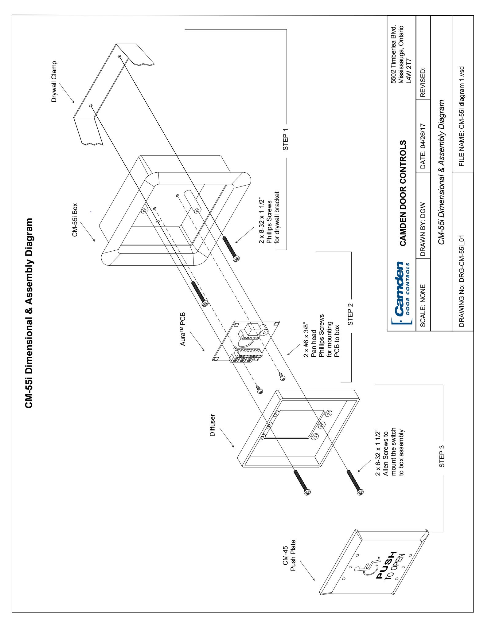
- 1. Assemble the drywall clamp to the box as per diagram 1. Determine the wire access location and drill hole of sufficient size, or use center knock-out plug.
- 2. Using the template, cut a hole in the drywall. Pull the wiring through the access hole and push the box through until the drywall clamp is on the back of the drywall. Tighten the 8-32 screws until the box is firmly mounted.
- 3. Remove circuit board from package and locate into the box Pull the wire through the hole in the centre of the circuit board, and then secure with the two small selftapping screws (provided).
- 4.a Wire as per diagram 2 (typical installation). Route the switch wiring through opaque diffuser panel, and install diffuser panel into box. It should fit snuggly.
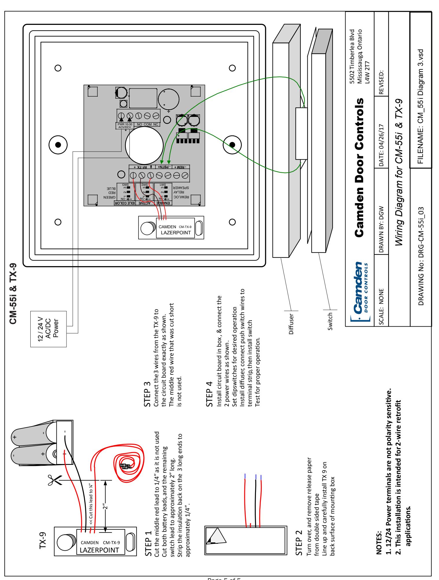
- 4.b If using a TX-9 transmitter to send the signal to an RX-91 or RX-92 Receiver, attach the transmitter and wire it before installing circuit board into the enclosure and fitting diffuser. See Diagram 3.
- 5. Screw in two #6-32 Allen-head screws (provided with switch) into the threaded center inserts, then attach wires to switch and install switch over screws. Using the Allen key (provided), locate the screws and tighten (by hand only).
- 6. Re-connect power and test for proper operation.
Section 4
Technical Data
Model CM-55i
Dimensions 6 1/2" H x 6 1/2" W x 2" D
(165 mm x 165 mm x 51 mm)
Construction Flame-resistant black ABS
(Insert – translucent ABS)
Finish Attractive pebble finish
Mounting 4 x #12 wood screws with anchors
Input Voltage 12 or 24V AC/DC
Output Voltage 3 Volts DC for TX-9 (only)
Current draw 150 mA (max)
Sounder 3200 ± 300 Hz @ 85 dB Lumina Red: 14.8 lumens, 1600 mW;
Green: 3.8 lumens, 330 mW,
Relay Contact 1 x Form C Contact Rating 3A @ 30 VDC
Section 5
Warranty
Camden Door Controls guarantees the Aura™ (CM-55i series) to be free from manufacturing defects for 3 years from date of sale.
If, during the first 3 years, the Aura™ fails to perform correctly, it may be returned to our factory where it will be repaired or replaced (at our discretion) without charge. Except as stated herein, Camden extends no warranties expressed or implied regarding function, performance or service.

Push Buttons Keypads Strikes Magnetic Locks Key Switches Relays & Timers Access Control


DISCOVER THE BEST IN DOOR ACTIVATING AND LOCKING PRODUCTS!
www.camdencontrols.com Toll Free: 1.877.226.3369
File: CM-55i Manual. indd Rev1 Revised: 05/05/17 Part No:40-82B209
Page 5 of 5