Camden CM-42-48 Series Switch Mounting Bollard Installation Instructions
Open the original PDF document
View PDF

Door Activation Devices
CM-42/CM-48 Series Switch Mounting Bollard
INSTALLATION INSTRUCTIONS
THIS PACKAGE INCLUDES:
- 1- CM-42/48 Mounting Bollard
- 1- Black Plastic End Cap with Black Elastic
- 1- Surface Mount Bracket
- 1- Allen Key
- 6- 1/4"-20 x 3/4" Stainless Steel Flat Head Socket Cap Screws
- 4- 1/2 x 3" Anchor Bolt
- 2- #8 x 1/2" Stainless Steel Flat Head Snake Eye Tapping Screws
- 2- #8 x 1/2" Stainless Steel Flat Head Phillips Tapping Screws
1. GENERAL DESCRIPTION
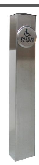
The Camden CM-42/48 Series switch post is a durable freestanding bollard suitable for mounting switches, keypads, etc. The switch may be hard-wired through conduit, or RF controlled.
2. SPECIFICATIONS
| Switch Preps | Single gang, column switch/custom prep. | ||
|---|---|---|---|
| RF Capability | Optional transmitter mounts under cap | ||
| Post Cap | 1/2" Black Acrylic | ||
| Material | Aluminum or stainless steel | ||
| Mounting |
1/2" Lag bolts into concrete or optional
in-ground base (10" long 1/2" rebar) |
||
| Finish | Clear or Bronze anodized or mill finish | ||
| Dimensions | CM-42 |
42" H x 6" W x 6" D
(1066.8mm x 152.4mm x 152.4mm) |
|
| CM-48 |
48" H x 6" W x 6" D
(1219.2mm x 152.4mm x 152.4mm) |
||
3. INSTALLATION
The post must be installed level and true. If the mounting surface is uneven or out of level, shim the base as required.
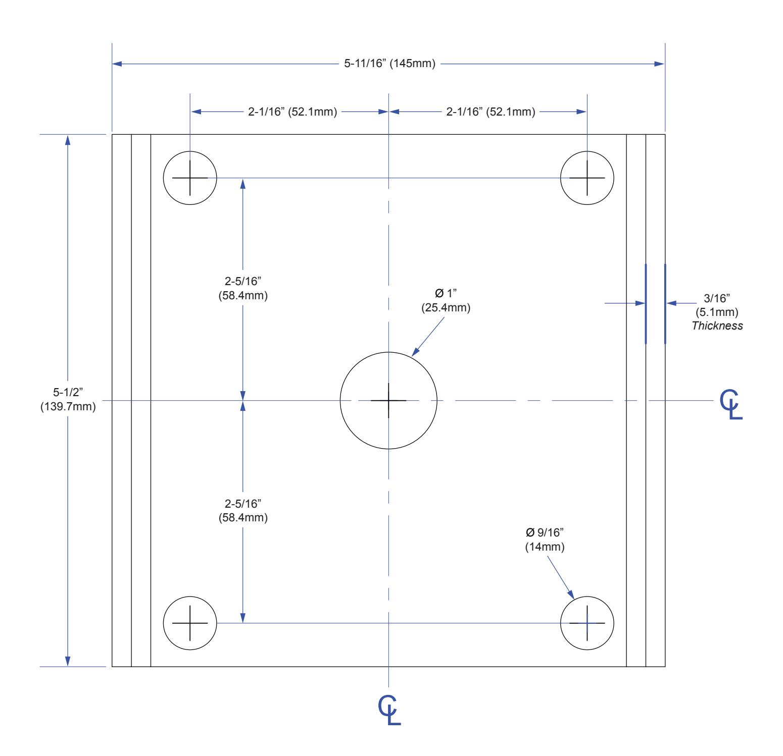
Use the base as a template to locate the four mounting holes. If mounting in concrete (recommended) drill 4 x 1/2" holes to accommodate the supplied concrete masonry anchors.
Position the four holes of the base over the four drilled holes in the concrete and tap in one 1/2" masonry anchor through each hole going through the base and into the concrete. Then tighten down the anchor bolts securely.
If installing the CM-42/CM-48 in-ground mounting base, note that at least 10" depth is required for the 1/2" rebar. Support the base level and true while the concrete cures.
Once the base is secure, slide on the post aligning the holes in the post with the base holes. Insert the eight 1/4"-20 stainless steel machine screws with the supplied Allen wrench.
If utilizing radio controls, fix the transmitter to the underside of the cap. Bring the two switch wires out the hole and attach to your switch.
Finally, mount the switch using the supplied stainless steel screws. It is strongly recommended to use a weather resistant modified switch for post mount applications.
4. WARRANTY
Camden Manufacturing guarantees the CM-42/CM-48 to be free from manufacturing defects for 3 years from date of sale. If during the first 3 years the CM-42/CM-48 fails to perform correctly, it may be returned prepaid to our factory where it will be repaired or replaced (at our discretion) without charge. Except as stated herein, Camden extends no warranties expressed or implied regarding function, performance or service.
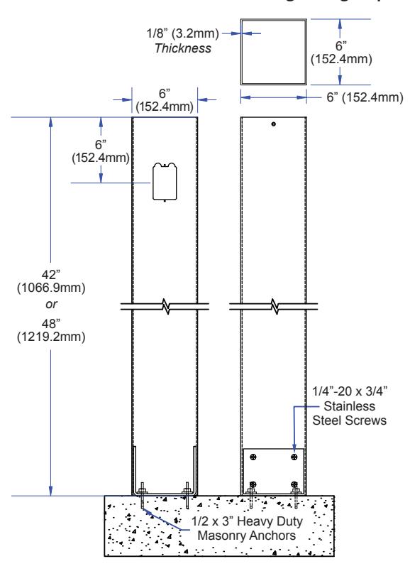
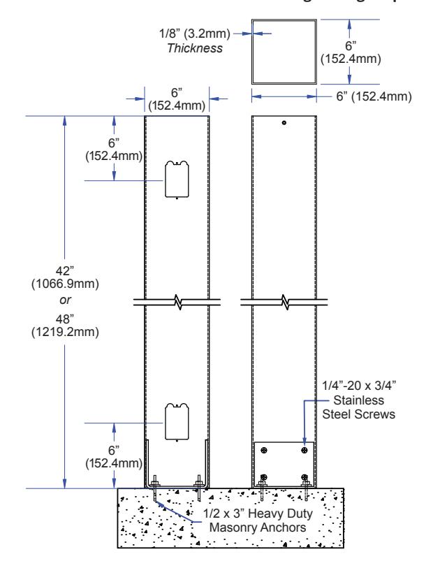
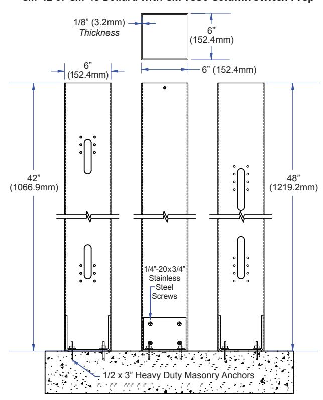
5. POST PREPARATION OPTIONS
CM-42 or CM-48 Bollard with one Single Gang Prep
CM-42 or CM-48 Bollard with Two Single Gang Prep
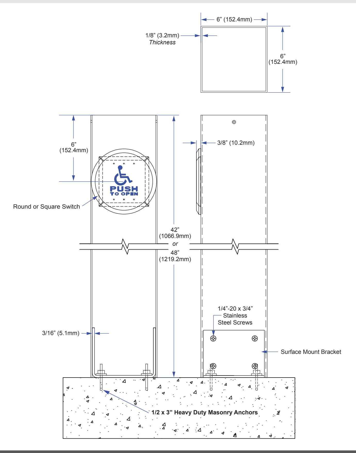
CM-42 or CM-48 Bollard with CM-7536 Column Switch Prep
CM-42 or CM-48 Bollard for Custom Prep
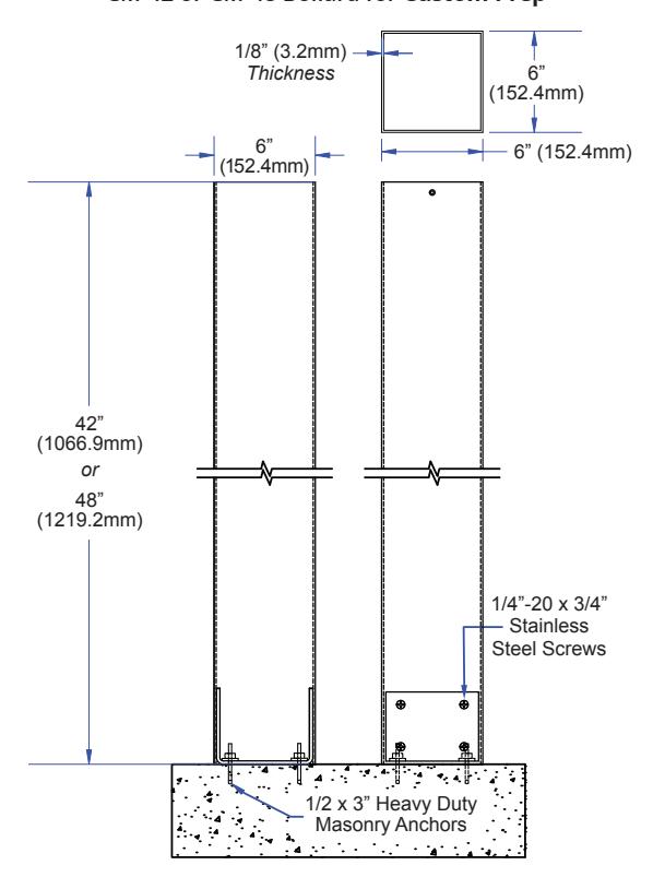
6. SWITCH POST INSTALLATION
7. ORDERING INFORMATION FOR REPLACEMENT PARTS
| ORDER INFORMATION | ||||||
|---|---|---|---|---|---|---|
| Item | Part Number | Description | ||||
| 1 | CM-42 / CM-48 | 42''/ 48'' Stainless Steel or Aluminum Mounting Bollard | ||||
| 2 | 60-42F003 |
(A) #8 x 1/2'' Stainless Steel Flat Head Snake Eye Tapping Screws (2)
(B) #8 x 1/2'' Stainless Steel Flat Head Phillips Tapping Screws (2) (C) Black Plastic End Cap with Black Elastic |
||||
| PARTS KIT | ||||||
| Item | Part Number | Description | ||||
| 3 | CM-42 & CM-48 Series |
(A) Allen Key
(B) 1/2 x 3'' Anchor Bolt (4) (C) 1/4-20 x 3/4" Stainless Steel Flat Head SOCKET CAP Screws (6) (D) #8 x 1/2'' Stainless Steel Flat Head Snake Eye Tapping Screws (2) |
||||
| 60-40A001 |
(E) #8 x 1/2'' Stainless SteelL Flat Head Phillips Tapping Screws (2)
(F) Surface Mount Bracket |
|||||
| ACTIVE SWITCH OPTIONS (SOLD SEPARATELY) | ||||||
| Item | Part Number | Material | Description | |||
| CM-45 Series | Stainless Steel | 4-1/2" Square Faceplate with Different Graphic Options | ||||
| 4 | CM-60 Series | Stainless Steel or Brass | 6" Round Stainless Steel Faceplate with Different Graphic Options | |||
| CM-7536 | Aluminum, Stainless Steel or Anodized Blue | 36'' Long Column Switch with Different Graphic Options | ||||
| ACTIVE SWITCH GRAPHIC & TEXT OPTIONS | ||||||
| Item | Part Number | Description | ||||
| 5 | CM-45 & CM-60 Series | |||||
| CM-xxx/1 | 'Blank' Faceplate | |||||
| CM-xxx/2 | 'WHEELCHAIR' Symbol, Blue Graphics | |||||
| CM-xxx/2AL | 'WHEELCHAIR' Symbol with Arrow Left, Blue Graphics | |||||
| CM-xxx/2AR | 'WHEELCHAIR' Symbol with Arrow Right, Blue Graphics | |||||
| CM-xxx/A2 | 'ACTIVE WHEELCHAIR' Symbol, Blue (CM-45 Series Only) | |||||
| CM-xxx/3 | 'PUSH TO OPEN' Text, Black Text | |||||
| CM-xxx/3F | 'POUSSEZ POUR OUVRIR' Text, Black Text | |||||
| CM-xxx/4 | 'WHEELCHAIR' Symbol and 'PUSH TO OPEN' Text, Blue Graphics | |||||
| CM-xxx/4F | 'WHEELCHAIR' Symbol and 'POUSSEZ POUR OUVRIR' Text, Black Graphics | |||||
| CM-xxx/4AL | 'WHEELCHAIR' Symbol and 'PUSH TO OPEN' Text with Arrow Left, Blue Graphics | |||||
| CM-xxx/4AR | 'WHEELCHAIR' Symbol and 'PUSH TO OPEN' Text with Arrow Right, Blue Graphics | |||||
| CM-xxx/A4 | 'ACTIVE WHEELCHAIR' Symbol and 'PUSH TO OPEN' Text, Blue (CM-45 Series Only) | |||||
| CM-xxx/8 | 'PUSH TO LOCK' Text, Black Text | |||||
| CM-xxx/8B | 'LOCK' Symbol and 'PUSH TO LOCK' Text, Red Graphics | |||||
| CM-xxx/8D | 'PUSH TO LOCK DOOR' Text, Black Text | |||||
| CM-xxx/8F | 'POUSSEZ POUR VERROUILLER' Text, Black Text | |||||
| CM-7536 Series | Description | |||||
| CM-xxx/2 | 'WHEELCHAIR' Symbol, Blue Graphics | |||||
| CM-xxx/4 | 'WHEELCHAIR' Symbol and 'PUSH TO OPEN' Text, Blue Graphics | |||||
8. MOUNTING BASE TEMPLATE
Call: 1.877.226.3369 / 905.366.3377