Camden CM-3000 Series Illuminated Switches Single Gang and Jamb Width Installation Instructions
Open the original PDF document
View PDF


CM-3000 Series Illuminated Switches Single Gang and Jamb Width Installation Instructions
| Package Contents | |||
|---|---|---|---|
| Model # | CM-3000 | CM-3010 | CM-3020 |
| CM-3030 | CM-3040 | CM-3050 | |
| CM-3100 | CM-3110 | CM-3120 | |
| Part | CM-3130 | CM-3140 | CM-3150 |
| Orange | - | 1 | 1 |
| Wire | |||
| Blue | 1 | - | 1 |
| Wire | |||
| Grey | 1 | 1 | 2 |
| Wire | |||
| In-line | 1 | 1 | 1 |
| Resistor | |||
| 6-32x¾" | 2 | 2 | 2 |
| FLT HD | |||
| Screws | |||
Description
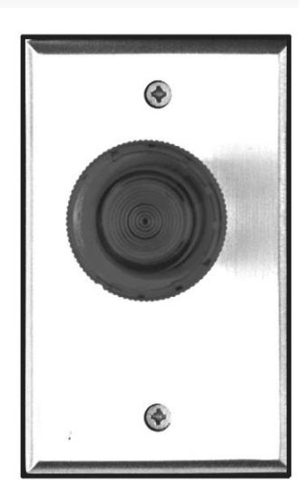
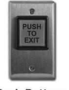
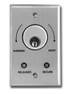
Camden Door Controls CM-3000 Series Exit Switches are heavy duty pushbuttons designed for industrial and commercial applications, where illumination is required. Buttons are 1 5/8" (40mm) in diameter, and are available in red or green (other colors on request). The faceplate is 1/4" thick brushed aluminum, in 1 3/4" or 2 3/4" widths. Optional duranodic (US40) finish is also available. CM-3000 Series switches utilize UL listed
switch components. Finished models comply with UL61058 Standard for Switches. Rated 10 amps @ 30 VDC, either momentary or maintained operation.
Application
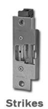
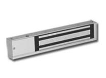
Camden illuminated Exit Switches are ideal for high traffic areas such as building front entrances and exits, as well as institutions, such as hospitals where an illuminated button is required. They can be surface, flush, or mullion (narrow stile) mounted. Camden Illuminated Exit switches are designed to control electric locks, electro-magnetic locks, electric strikes, automatic doors, and handicap operators. They may also be used for automatic doors, shunting, bypassing alarms, request-to-exit, timed functions, and many other applications.
Installation
CM-3000, CM-3010, CM-3020, CM-3030, CM-3040 and CM-3050 are supplied with a brushed aluminum faceplate that can be easily mounted to a single gang electrical box.
CM-3100, CM-3110, CM-3120, CM-3130, CM-3140 and CM-3150 are supplied with 1-3/4" brushed aluminum faceplate for door jamb mounting.
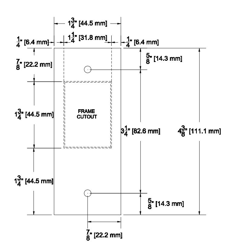
Figure 1 shows the cutout required for door jamb mounting.
CM-3000 Illuminated Switches Installation Instructions
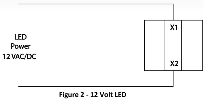
LED Wiring
For 12 V AC or DC power connections, please connect you LED power leads directly to the center wiring terminals (X1 and X2) as shown in Figure 2.
For 24 V AC or DC power connections, please use the supplied resistor in-line with one of the two center wiring terminals (X1 or X2) as shown in Figure 3.
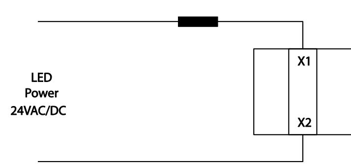
Figure 3 - 24 Volt LED
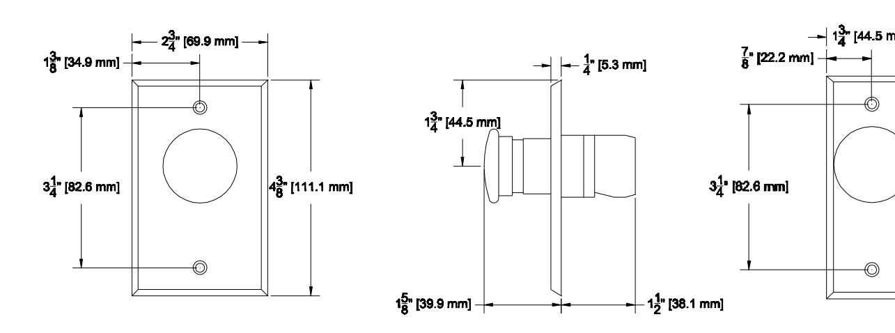
Figure 4 – Single Gang Front
Figure 5 – Side View Figure 6 – Narrow Style Front
WARNING : Do NOT apply power to the unit until all wiring is complete.
www.camdencontrols.com Toll Free: 1.877.226.3369
Series