Camden CM-120TX Wireless Digital Keypads Installation Instructions
Open the original PDF document
View PDF


CM-120TX Wireless Digital Keypads Installation Instructions
Package Contents
- (1) Keypad and faceplate assembly
- (1) Foam gasket (CM-120W only)
- (2) #6-32 x 1" S/S Phillips screws
- (2) #6-32 x 1" Tamperproof screws
- (1) Tamperproof screwdriver
- (1) Battery Holder
- (2) AA Batteries
Section 1__________________ General Description
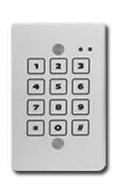
The CM-120TX is an outdoor illuminated battery operated wireless all metal keypad. It is a versatile self-contained, single-gang, stand-alone keypad mounted on a heavy stainless steel, single gang faceplate. It features up to 999 users, and offer over 1,000,000 possible user codes (from one to eight digits). It operates on 2 x 1.5V 'AA' batteries providing for up to 90,000 operations (based on an average 4 digit PIN followed by *). The CM-120TX is compatible with our 915 MHz Lazerpoint RFTM products. It provides 2 separate RF codes that can be transmitted individually. It has non-volatile memory to retain user settings when the batteries discharge or when they are being changed.
Section 2__________________ Installation
Mounting
The CM-120TX has been designed to fit into a standard single gang electrical box. The terminal strips are carefully positioned so all wiring exits out the back, so it won't interfere with, or short out on, the sides of the box.
Wiring
Camden CM-120TX is supplied with an AA battery holder. Connect the battery holder as shown with the Red wire connecting to terminal 1(+) and the Black wire connecting to terminal 2(-). Insert the batteries into the battery holder as shown in Figure 1.
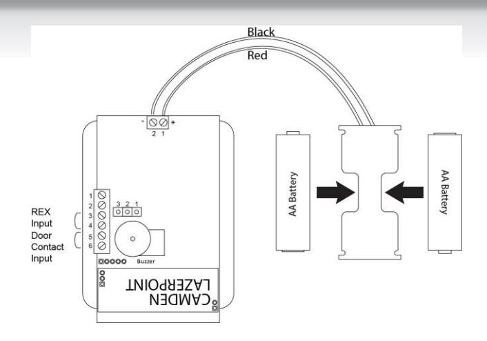
Figure 1 CM-120TX Power Connections
Section 3__________________ How to Program Keypad
Using This Manual
- Brackets and spaces are not part of programming or user codes. They are used here to clarify the operations and group like functions.
- Square brackets [ ] are used to indicate that the keys inside the brackets are to be pressed at the same time. (Requiring two keys to be pressed simultaneously reduces the chance that someone will accidentally get into programming mode.)
- When entering a code in brackets, first press the star key and, while holding down the star key, press the second key. Release them both together.
Using the Keypad
Each user on the system is assigned two different numbers. The first is the User Number, which he/she does not use directly. This number, from 1 to 999, is used to keep track of who is assigned to the system, using the schedule on Page 8. All leading zeroes are ignored. The second is the User Code, a 1 to 8 digit programmable code that the user will enter into the keypad to activate certain functions. This code can have leading zeroes as part of the code. This information should be recorded and stored in a safe place for future
reference. The keypad can support a total of 999 users, from 1 to 999 (See chart on page 10).
User number one belongs to the Master User and has a default user code of 1234. Note that the master user code is used for administration ONLY, and will not (normally) operate the wireless outputs. When a global disable is engaged (all users locked out), the master code will still operate wireless output one.
User number two will toggle the global enable/disable function when prefixed by two or more pound ('#') keys. This allows lockout of all other codes (user two will still be able to operate the keypad normally, even when the global lockout is engaged). Therefore, user number two should be reserved for use by a manager. When entered without the prefixed '#'s, the code of user number 2 operates the keypad in the same way as the other users do.
When using the keypad with variable-length user codes, it is necessary for the user to press the star (*) key after the User Code has been entered. This indicates the end of the code, and causes the keypad to attempt to validate the entered code. If the number entered is valid, the keypad will perform the programmed function (e.g., activate the relay).
For example, to operate the keypad using the user code 4321 (which must be entered as a user code in programming mode first), enter 4321*. While the door is unlocked, or whatever job your unit is to perform, the green LED will blink at a slow rate. Note that the star key can be substituted with another digit of your choice. (See 0# Set Enter Key )
Understanding the LEDs
The three Light Emitting Diodes (LED's) above the keypad provide information on the status of the unit. NOTE: A 'slow' flash is once every two seconds and a 'fast' flash is once every second.
GREEN LED:
'ON' Solid: No errors, output is
active.
'FAST FLASHING': Keypad is in
programming mode.
RED LED:
'ON' Solid: Error condition.
See chart at end of
this manual.
YELLOW LED:
To meet ADA requirements, both a visual and audible key-press confirmation is provided (blinks on each key-press). This can be enabled or disabled
during programming. See the [*6] 0 # programming option for more details.
Checking the Battery Level
The Cm-120TX has a built-in battery gauge. Press and hold the any button for 5 seconds. The Green LED will flash and the buzzer will beep up to 5 times indicating the battery level.
5 Beeps = Fully charged batteries
1 Beep = Replace the batteries
The CM-120TX will beep if the Low Battery Alarm(page 4) is enabled.
SET-UP INSTRUCTIONS:
Note:
- 1. Keep careful track of User Codes and to whom they are assigned, assigned outputs, etc. as you program them, and keep the list in a safe place.
- 2. Press the buttons firmly.
- 3. Whenever the * and any other character are included in brackets [* x], press the * first and, while holding the * down, press the other key. Release both keys together.
[*1] Enter Program Mode (First Step)
Press * and 1 at the same time. Enter the Master Code (1234 is the factory default), then *. The green LED should now be rapidly flashing.
The keypad will remain in program mode until no key is pressed for approximately 30 seconds. To exit programming mode quickly, press the special sequence – " * # * ".
For example, [* 1] 1 2 3 4 * will put the keypad in program mode.
[*1] Administration Functions
Set Code Length - Function 1#
Default: 0 (variable code length)
When set to zero, user codes can vary from 1 to 8 characters, but must be terminated by pressing the "enter key", which by default is ' * '. When set from 1 to 8, all user codes must use the programmed length, but will not require termination by the programmed "enter key" .
(User codes shorter than the maximum are still allowed, but the user must terminate it with the current "enter" key).
For example, [*1] 1 # 4 * will set all user codes to a fixed 4-digit length.
Set Enter Key - Function 0#
Default: ' * '
If the code length has been left at 0 (see above), then use this feature to select the "enter" key used to terminate user code entry. The default setting is ' * ', but it can be changed to any key on the keypad (select carefully).
For example, [*1] 0 # # * will change the user code enter key to '#'.
Incorrect Code Count Alarm - Function 2#
Default: 0 (disabled)
When set to zero, the keypad will not alarm on entry of invalid codes. When set to a value between 1 and 20, the keypad will generate an alarm after the specified number of invalid codes have been entered, within two minutes.
For example, [*1] 2 # 6 * will set the keypad to generate an alarm when 6 invalid user codes have been entered. NOTE: This setting also requires the "Incorrect code alarm Lockout" feature enabled. See 5# on page 4.
Force Unique User Codes - Function 3#
Default: 1 (Enabled)
When set to zero, the keypad will accept any user code for each user. When set to one, during programming of new user codes, the keypad will check the desired code against all currently programmed users, and only accept the user code if it is unique. Attempting to program a code that is not unique will cause an error alarm, and the programming procedure must be restarted and a different code selected.
NOTE: When enabling this mode (when previously disabled), it is recommended the administrator erase all settings back to factory defaults first , to ensure all user codes are unique. Failure to perform this step may leave duplicate user codes among those already learned, and result in unexpected operation.
0 = disabled
1 = enabled
For example, [*1] 3 # 0 * will disable "Force Unique User Codes".
Backlight Control Enable/ Disable - Function 5#
Default: 0 (disabled)
Enable or disable backlight control on keypress.
When enabled, the backlight will be OFF until the first keypress. It will remain on for 5 seconds after the last keypress. When disabled, the backlight will remain OFF.
0 = disabled
1 = enabled
To enable/disable Backlight Control mode:
First, enter program mode. Then enter [*1], then 5#, then 0 to disable, or 1 to enable, then *.
For example, [*1] 5 # 1 * will make the backlighting turn ON after the first key press. The backlighting will remain ON for 5 seconds after the last key press.
User Two "Global Lockout" - Function 6#
Default: 1 (Enabled)
When enabled, user #2 (a manager, for instance) can lockout all other users by prefixing his code by two (or more) "#" keys. When a global lockout is engaged, no user code will activate the outputs, except user #1 & #2. Programming functions, and request to exit (REX) are not disabled. This can be used (for instance) to immediately control all access while changing selected user codes in case of a security problem, or for lockout over a weekend.
To disable user two "global lockout" feature:
First, enter program mode. Then enter [*1], then 6#, then 0 to disable, or 1 to enable, then *.
0 = disabled
1 = enabled
For example [*1] 6 # 0 * will disable user #2's ability to engage a global lockout.
Note: When user number #2's key code is prefixed with two or more '#'s, the "Global User Enable/ Disable" flag will be toggled.
Channel Output Mode - Function 7#
Default: 0 (Channel 1 Only)
This control allows the installer to select the channel output mode. Chosing the default (0) means that a valid code activates Channel 1 only.
Setting the Channel Output Mode to "1" will allocate the first 499 user numbers (memory addresses) to Channel 1, and the remaining 500 user numbers to Channel 2.
To choose the Relay Output mode:
First, enter program mode. Then enter [*1], then 7#, then 0 for Relay 1 only, 1 for split output, or 2 for both relays sequenced, then *.
0 = Channel 1
1 = 1 - 499 = Channel 1, 500 – 999 = Channel 2
For example [*1] 7 # 1 * will allocate any user number from 1 – 499 to Channel 1, and any user number from 500 – 999 to Channel 2.
[*2] Add/Change/Delete Users
To add or change a user:
First, enter program mode (see First Step above), then enter [*2], then the user number you wish to add or change (from 1 to 999 inclusive) followed by #. Finally, enter the new User Code (up to 8 digits), followed by *, then the new User Code again (for verification), followed by *. User Codes may only contain digits 0 through 9 (* and # may not be used as part of the code, except when programmed as the "enter" key).
Example: [*2] 44 # 2125 * 2125 * will assign a user number of 44 and a user code of 2125.
To delete a user code:
First, enter program mode. Then enter [*2], then the user number you wish to delete (from 2 to 999, inclusive), then press #, then *, then *.
For example, [*2] 75 # * * will delete the user code and all assignments for user number 75.
PLEASE NOTE: The Master Code cannot be deleted but it may be changed.
Example: [*2] 1 # 38714 * 38714 * will change the Master Code to 38714. If you change it, don't forget it.
[*3] Time Delay/Duration Functions
Door Prop open Alarm Delay - Function 2#
Default: Disabled
Sets the delay (1 to 255 seconds) before open door contacts are considered an alarm condition. ( NOTE: Door contacts are required for this feature.)
To program the door open alarm delay:
First, enter program mode. Then enter [*3], then 2#, then the delay time in seconds (0=disabled), then *.
For example, [*3] 2 # 30 * will set the door open alarm delay to 30 seconds.
NOTE: To turn this feature on/off, see section [*4] 3# Door Prop Open Alarm on the next page.
[*4] Alarm Control Functions
Incorrect code alarm - Function 0#
Default: 0 (Disabled)
Use to control how the "Incorrect code alarm" is annunciated.
0 = disabled
1 = buzzer
If the "Incorrect code alarm" is enabled, and triggered, a valid code is required to reset.
To program how the "incorrect code alarm" condition is annunciated:
First, enter program mode. Then enter [*4], then 0#, then the annunciation code, then *.
For example, [*4] 0 # 1 * will configure the keypad to indicate entry of the programmed count of invalid codes on the buzzer only.
Low Battery Alarm - Function 1#
Default: 1 (Enabled)
Enable or disable the "Low battery alarm".
0 = disabled
1 = buzzer
To disable the "low battery alarm":
First, enter program mode. (See "First Step" above) Enter [*4], then 1#, then the annunciation code, then *.
For example, [*4] 1# 0* will configure the keypad not to annunciate the low battery condition.
Stuck key alarm - Function 2#
Default: 0 (Disabled)
Enable or disable the "Stuck key alarm".
0 = disabled
1 = enable
The "Stuck key" alarm will activate the buzzer after 15 seconds (factory set delay) of the key being held continuously, and reset as soon as the key is released (or after 10 seconds, whichever occurs first)
To enable the "stuck key alarm":
First, enter program mode. Then enter [*4], then 2#, then (0 or 1), then *.
For example, [*4] 2 # 1 * will configure the keypad to activate the stuck key buzzer.
Door Prop open Alarm - Function 3#
Default: 0 (Disabled)
Use to control how the "Door prop open alarm" is annunciated.
0 = disabled
1 = buzzer
To program how the "Door Prop open alarm" condition is annunciated:
First, enter program mode. Then enter [*4], then 3#, then the annunciation code, then *.
For example, [*4] 3 # 1 * will annunciate the buzzer during the alarm.
NOTE 1: this feature requires the use of the door contact input.
NOTE 2: The alarm will sound continuously until reset. To reset, enter valid code.
NOTE 3: To set Delay Time, see [*3] 2# on Page 4.
Incorrect code alarm lockout - Function 5#
Default: 0 (Disabled)
Use to configure the incorrect code alarm lockout.
0 = disabled 1 = enabled
To program:
First, enter program mode. Then enter [*4], then 5#, then the enable/disable code, then *.
For example, [*4] 5 # 1 * will configure the keypad to lockout for 2 minutes (factory set lockout duration), after the incorrect code count alarm limit is reached. During the lockout period, all keypad entry (including correct codes) is ignored.
There is an automatic reset after 2 minutes.
(See 2# on Page 3 of manual for setting code count)
Door Forced open Alarm - Function 6#
Default: 0 (Disabled)
Use to control how the "Door forced open alarm" is annunciated.
0 = disabled
1 = buzzer
To program how the "Door forced open alarm" condition is annunciated:
First, enter program mode. Then enter [*4], then 6#, then the annunciation code, then *.
For example, [*4] 6 # 1 * will configure the keypad to sound an alarm if the door is forced open (without entering a valid code).
NOTE 1: this feature requires the use of the door contact input.
NOTE 2: The alarm will sound continuously until reset.
[*6] Annunciation Control Functions
Yellow LED Enable - Function 0#
Default: 1 (Enabled)
Enable or disable the yellow LED. When enabled, the yellow LED illuminates when any key is pressed.
0 = disabled
1 = enabled
To disable the yellow LED:
First, enter program mode. Then enter [*6], then 0 #, then 0 to disable, or 1 to enable, then *.
For example, [*6] 0 # 0 * will disable yellow LED illumination.
Buzzer Enable / Disable - Function 1#
Default: 1 (Enabled)
Enable or disable the buzzer. When disabled, the buzzer will not sound for any condition
0 = disabled
1 = enabled
To disable the buzzer:
First, enter program mode. Then enter [*6], then 1#, then 0 to disable, or 1 to enable, then *.
For example, [*6] 1 # 0 * will disable the buzzer for all conditions.
Correct Code Audio Tone - Function 2#
Default: 0 (Disabled)
Enable or disable the audio tone annunciating correct code entry. When enabled, a single 2 tone beep will sound when a correct code has been entered. In the case of toggled mode, the audio tone will last for 8 seconds (hard-coded) when a correct code toggles relay one ON; the audio tone will be a single two-tone beep, "do-ray", when a correct code toggles relay one OFF.
0 = disabled
1 = enabled
To enable the audio tone on correct code entry: First, enter program mode. Then enter [*6], then 2#, then (0 to disable, or 1 to enable), then *.
For example, [*6] 2 # 1 * will enable the audio tone on correct code entry.
Incorrect Code Audio Tone - Function 3#
Default: 1 (Enabled)
Enable or disable the audio tone annunciating correct code entry. When enabled, an audio tone will sound when any incorrect code has been entered, for the duration that the red LED is illuminated.
0 = disabled
1 = enabled
To disable the audio tone on incorrect code entry:
First, enter program mode. Then enter [*6], then 3#, then 0 to disable, or 1 to enable, then *.
For example, [*6] 3 # 0 * will disable the audio tone on incorrect code entry.
Request to Exit Audio Enable/ Disable - Function 5#
Default: 0 (Disabled)
Enable or disable audio annunciation for Channel #1 when a Request to Exit signal is input. When enabled, if Channel 1 is triggered by REX input, a looped tone (do-ray) will be annunciated for the duration that Relay #1 is energized. In the case of Toggled mode, the annunciation will last for 8 seconds (hard-coded). In the case of entering into Unlocked Mode (REX input held for more than 15 seconds), 4 beeps will sound after the looped two-tone annunciation. A single ("Ray-Do") tone will sound when exiting Unlock Mode.
0 = disabled 1 = enabled
To enable/disable REX Audio Annunciation:
First, enter program mode. Then enter [*6], then 5#, then 0 to disable, or 1 to enable, then *.
For example, [*6] 5 # 1 * will enable the audio annunciation for REX input.
FACTORY DEFAULT SETTINGS
If the settings have not been changed after shipment, or if they have been reset, they are as follows:
- o Master User # 1 Code is 1234.
- o Main Channel = 3 sec
- o Secondary Channel = programmable.
- o Yellow LED enabled.
Reset to Factory Defaults
Reset the Master Code:
While holding the # and * down together for aprox. 4 secs, power up the keypad. There will be 4 beeps and all LED's will flash. The keypad will immediately move into the battery life indicator. It will beep up to 5 times and the green LED will flash.
Reset the keypad to factory defaults:
While holding down the # and * for approx. 10 seconds. Power up the keypad. There will be the
initial 4 beeps at the 4 second point, indicating the Master Code is reset (1234), followed by the battery test beeps (up to 5), then followed by 8 beeps indicating the keypad has been reset to factory defaults.
[*9] Erase Keypad Memory/Reset ALL to Factory
Force factory default settings (use with caution)
This is used when most or all of the programming has to be changed, as when a keypad has been moved to a new location. To reset to factory defaults.
First, enter program mode. Then enter [*9], then reenter the master keycode, then *.
For example, [*9] 1 2 3 4 * will immediately and permanently clear the entire memory (assuming the master keycode has not been changed from the factory default. Once this function has been executed, there is NO WAY to restore the previous state.
Section 4 _________________
Technical Data
| Model | CM-120TX | ||
|---|---|---|---|
| Illumination |
No
/ Yes |
||
| Size |
2 ¾" x 4 ½" x ¾"
69.85mm x 114.30mm x |
||
| 19.05mm | |||
| Mounting |
2 x #6-32 machine
security |
||
| screws | |||
| Temperature |
-40° -
+185°F (-40° - +85°C) |
||
| Operating voltage | 2 x AA Alkaline Batteries | ||
| Battery Life | 90,000 Operations | ||
| Based on a 4 digit user code | |||
| Capacity | 999 User codes | ||
| Length | Up to 8 digits (10 million | ||
| possible codes) | |||
| Response time | 0.3 seconds | ||
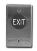
| Inputs |
1 x REX input
1 x Door Contact input |
||
| Output |
RF
Only, 2 Channels |
||
| Channel 1 assigned to users | |||
|
1 -
499 |
|||
| Channel 2 assigned to users | |||
|
500 -
999 |
|||
Warranty
Camden Door Controls guarantees the CM-120TX to be free from manufacturing defects for 3 years from date of sale. If during the first 3 years the CM120TX fails to perform correctly, it may be returned to our factory where it will be repaired or replaced (at our discretion) without charge. Except as stated herein, Camden extends no warranties expressed or implied regarding function, performance or service.
Troubleshooting Tips
- o If you make an input error (e.g. if you enter a non-existent User Code) and press the star key, the red LED will light. Simply start over.
- o If you make an input error and have not yet entered *, just wait 5 seconds, and the command memory will be cleared automatically. Start again. You will not increment the error count.
- o The "Lockout-on-#-errors" feature is disabled by default. This will prevent the keypad from hanging up if anyone plays with the keypad in certain applications.
- o Do not make the mistake of thinking you have to 'clear' the red light if you make an error. Just re-enter the correct number. The red LED will clear automatically with the first key you press.
- o Be sure you are pressing the buttons firmly. The yellow LED should come on and an audio tone should sound with each key pressed, unless these features have been disabled.
Questions?
Visit us online at www.camdencontrols.com Call us toll-free at 1-877-CAMDEN9 or (905)366-3377

5502 Timberlea Blvd., Mississauga, ON Canada L4W 2T7
www.camdencontrols.com Toll Free: 1.877.226.3369
File: CM-120TX_NF_Man_Rev1.docx Firmware Version: 1.08 Revised: December 16, 2014 Part No.: 40-82B166
| Name |
Memory
address |
User
Code |
Name |
Memory
Address |
User
Code |
|---|---|---|---|---|---|
| Master User | 1 | 1234 | 45 | ||
| Manager | 2 | 46 | |||
| User #1 | 3 | 47 | |||
| User #2 | 4 | 48 | |||
| etc | 5 | 49 | |||
| 6 | 50 | ||||
| 7 | 51 | ||||
| 8 | 52 | ||||
| 9 | 53 | ||||
| 10 | 54 | ||||
| 11 | 55 | ||||
| 12 | 56 | ||||
| 13 | 57 | ||||
| 14 | 58 | ||||
| 15 | 59 | ||||
| 16 | 60 | ||||
| 17 | 61 | ||||
| 18 | 62 | ||||
| 19 | 63 | ||||
| 20 | 64 | ||||
| 21 | 65 | ||||
| 22 | 66 | ||||
| 23 | 67 | ||||
| 24 | 68 | ||||
| 25 | 69 | ||||
| 26 | 70 | ||||
| 27 | 71 | ||||
| 28 | 72 | ||||
| 29 | 73 | ||||
| 30 | 74 | ||||
| 31 | 75 | ||||
| 32 | 76 | ||||
| 33 | 77 | ||||
| 34 | 78 | ||||
| 35 | 79 | ||||
| 36 | 80 | ||||
| 37 | 81 | ||||
| 38 | 82 | ||||
| 39 | 83 | ||||
| 40 | 84 | ||||
| 41 | 85 | ||||
| 42 | 86 | ||||
| 43 | 87 | ||||
| 44 | dditional conia | 88 |