Camden CM-110SK Standalone Keypad Installation Instructions
Open the original PDF document
View PDF

Camden DOOR CONTROLS
CM-110SK Standalone Keypad Installation Instructions
1. Packing List
| Qty | Name | Remarks |
|---|---|---|
| 1 | Keypad | |
| 1 | User manual | |
| 1 | Screwdriver | 0.8" x 2.4" (20 mm×60 mm) |
| 2 | Wall plugs | 0.24" x 1.2" (6 mm×30 mm) |
| 2 | Self-tapping screws | 0.16" x 1.1" (4 mm×28 mm) |
| 1 | Torx screw | 0.12" x 0.24" (3 mm×6 mm) |
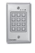
2. Description
The CM-110SK is a multifunctional standalone keypad with a wiegand output for interfacing to an access control system. It is suitable for mounting in either indoor or outdoor harsh environments. It is housed in a strong, sturdy and vandal proof Zinc Alloy electroplated case. The electronics are fully potted so the unit is waterproof and conforms to IP68. This unit supports up to 2000 users with a 4 digit PIN. The unit has many extra features including lock output current short circuit protection, wiegand output, and a backlit keypad. These features make the unit an ideal choice for commercial and industrial applications such as factories, warehouses, laboratories, banks and prisons.
3. Features
- 2000 users, 4 digit PIN
- Backlit keys
- · Zinc Alloy Electroplated anti-vandal case
- Waterproof, conforms to IP68
- · Easy to install and program
- Full programming from the keypad
- Can be used as a stand-alone keypad
- Wiegand 26 input for connection to external reader
- Wiegand 26 output for connection to a controller
- Adjustable Door Output time, Alarm time, Door Open time
- Very low power consumption (30mA)
- Fast operating speed, <20ms with 2000 users
- Lock output current short circuit protection
- · Built in light dependent resistor (LDR) for anti-tamper
- · Built in buzzer
- Red, Yellow and Green LEDS display the working status
4. Quick Reference Programming Guide
| To enter programming mode |
*
Master Code # 999999 is the default factory master code |
|
|---|---|---|
| To exit from the programming mode | * | |
| Note: You must be in programming mode to program the following feature | ||
| To change the master code |
0
New Code # New Code The master code can be 6 to 8 digits |
|
| To add a PIN user |
1
User ID Number # PIN The ID number is any number between 1 & 2000. The PIN is any four digits between 0000 & 9999 with the exception of 1234 which is reserved. Users can be added continuously without exiting programming mode. |
|
| To delete a PIN user |
2
User ID Number # for a PIN user or Users can be deleted continuously without exiting programming mode. |
|
| To unlock the door for a PIN user | Enter the PIN then press # | |
5. Specifications
| Operating Voltage | 12V DC ±10% |
|---|---|
| User Capacity | 2,000 |
| Active Current | < 60mA |
| Idle Current | 25±5 mA |
| Lock Output Load | Max 3A |
| Alarm Output Load | Max 20 mA |
| Operating Temperature | -49°F to 140°F (-45°C to 60°C) |
| Operating Humidity | 10% - 90% RH |
| Waterproof | Conforms to IP 68 |
| Adjustable Door Relay time | 0 - 99 seconds |
| Adjustable Alarm Time | 0 - 3 minutes |
| Wiegand Interface | Wiegand 26 bit |
| Wiring Connections | Electric Lock, Exit Button, External Alarm, External Reader |
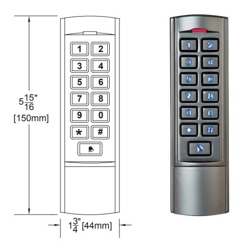
| Dimensions | 5 15/16" H x 1 3/4" W x 1" D (150 mm x 44 mm x 25 mm) |
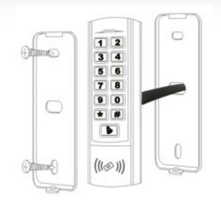
6. Installation
- Remove the back cover from the keypad using the supplied special screw driver
- Drill 2 holes on the wall for the Self tapping screws and 1 hole for the cable
- Put the supplied wall plugs into the two holes
- Fix the back cover firmly on the wall with the 2 Self tapping screws
- Thread the cable through the cable hole
- Attach the keypad to the back cover

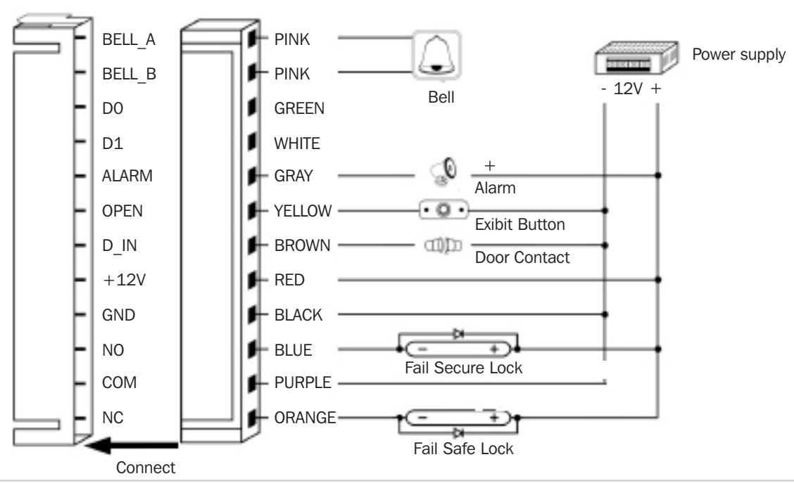
| Color | Function | Description | |
|---|---|---|---|
| Pink | BELL_A | Doorbell | |
| Pale Blue | BELL_B | Doorbell | |
| Green | D0 | Wiegand output D0 | |
| White | D1 | Wiegand output D1 | |
| Grey | ALARM | Alarm negative (alarm positive connected 12 V+) | |
| Yellow | OPEN | Exit button (the other end connected GND) | |
| Brown | D_IN | Door Contact switch (the other end connected GND) | |
| Red | 12V+ | 12V + DC Regulated Power Input | |
| Black | GND | 12V - DC Regulated Power Input | |
| Blue | NO | Relay Normally Open | |
| Purple | COM | Relay Common | |
| Orange | NC | Relay Normally Closed | |
Common power supply diagram:
8. Reset to Factory Default
- a. Disconnect power from the unit
- b. Press and hold # key while powering the unit back up
- c. On hearing two "Beeps" release # key, system is now back to factory settings
Note: Only the installer data is restored, user data will not be affected.
9. Anti-Tamper Alarm
The unit uses a LDR (light dependent resistor) as an anti-tamper alarm. If the keypad is removed from the cover, the tamper alarm will operate.
10. Sound and Light indication
| Operation Status | Red Light | Green Light | Yellow Light | Buzzer |
|---|---|---|---|---|
| Power on | - | Bright | - | Beep |
| Standby | Bright | - | - | - |
| Press keypad | - | - | - | Beep |
| Operation successful | - | Bright | - | Beep |
| Operation failed | - | - | - | Beep/Beep/Beep |
| Enter into programming mode | Bright | - | - | - |
| In the programming mode | - | - | Bright | Beep |
| Exit from the programming mode | Bright | - | - | Beep |
| Open the door | - | Bright | - | Beep |
| Alarm | Bright | - | - | Alarm |
11. Detailed Programming Guide
11.1 User Settings
| To enter the programming mode |
*
Master code # |
|
|---|---|---|
| 999999 is the default factory master code | ||
| To exit from the programming mode | * | |
| Note that to undertake the following programming, the master user must be logged in | ||
|
0
New code # New code # |
||
| To change the master code | The master code can be 6 to 8 digits long | |
|
1
User ID number # PIN # The ID number is any number between 1 & 2000. The PIN is any four digits between 0000 & 9999 with |
||
| To add a Pin user |
the exception of 1234 which is reserved. Users can be
added continuously without exiting programming mode as follows: |
|
|
1 User ID no 1
# PIN # User ID no 2 # PIN # |
||
| To delete a PIN user |
2
User ID number # Users can be deleted continuously without exiting programming mode |
||
|---|---|---|---|
|
To change the PIN of a PIN user
(This step must be done out of programming mode) |
*
ID number # Old PIN # New PIN # New PIN # |
||
| To delete All users | |||
|
To delete ALL users. Note that this is a dangerous
option so use with care |
2
0000 # |
||
| To unlock the door | |||
| For a PIN user | Enter the PIN then press # | ||
| Relay Output Delay Time | |||
|---|---|---|---|
| * Master code # 4 0~99 # * | |||
| To set door relay strike time | 0-99 is to set the door relay time 0-99 seconds | ||
| Door Open Detection | |||
|
Door Propped Open Alarm. When used with an optional magnetic contact or built-in magnetic contact of the lock, if
the door is opened normally, but not closed after 1 minute, the inside buzzer will beep automatically to remind people to close the door and continue for 1 minute before switching off automatically. |
|||
|
Door Forced Open Alarm. When used with an optional magnetic contact or built-in magnetic contact of the lock,
if the door is opened by force, or if the door is opened after 20 seconds of the electro-mechanical lock not being closed properly, the inside buzzer and alarm output will both operate. The Alarm Output time is adjustable between 0~3 minutes with the default being 1 minute. |
|||
| To disable door open detection. (Factory default) |
6
0 # |
||
| To enable door open detection |
6
1 # |
||
| Alarm output time | |||
|
To set the alarm output time (0~3 minutes)
Factory default is 1 minute |
5
0~3 # |
||
|
Keypad Lockout & Alarm Output options. If there are 10 invalid cards or 10 incorrect PIN numbers in a
10 minute period either the keypad will lockout for 10 minutes, or the alarm will operate for 10 minutes, depending on the option selected below. |
|||
|
Normal status: No keypad lockout or alarm
(factory default) |
7
0 # (Factory default setting) |
||
| Keypad lockout enable |
7
1 # |
||
| Alarm and inside buzzer operate |
7
2 # |
||
| To remove the alarm | |||
| To reset the Door Forced Open Alarm | Master Code # | ||
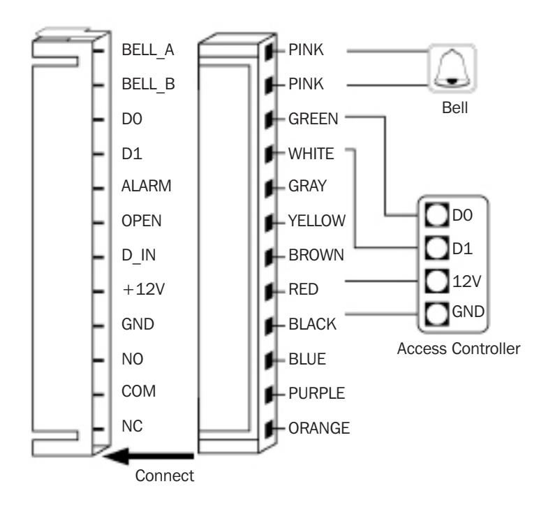
12. The unit operating as a Wiegand Output Reader
In this mode the unit supports a Wiegand 26 bit output so the Wiegand data lines can be connected to any controller which supports a Wiegand 26 bit input.
12.1 Keypad 8 bit Burst Mode
Every key pressed generates an 8 bit data stream that is transmitted over the wiegand bus.
| Key | Output | Key | Output |
|---|---|---|---|
| 0 | 11110000 | 6 | 10010110 |
| 1 | 11100001 | 7 | 10000111 |
| 2 | 11010010 | 8 | 01111000 |
| 3 | 11000011 | 9 | 01101001 |
| 4 | 10110100 | * | 01011010 |
| 5 | 10100101 | # | 01001011 |

Push Buttons Keypads Strikes Magnetic Locks Key Switches Relays & Timers Access Control
5502 Timberlea Blvd., Mississauga, ON Canada L4W 2T7
www.camdencontrols.com Toll Free: 1.877.226.3369
File: Standalone Keypad Installation Instructions.indd R1 Revision: 25/01/2016 Part No.: 40-82B191
Page 8 of 6