CX-WEC10K2 Manual
Open the original PDF document
View PDF

Electrified Locks, Relays and Timers
CX-WEC10K2
Emergency Control Kit
INSTALLATION INSTRUCTIONS
THIS PACKAGE INCLUDES:
1- CM-AF540SO (CM-450R/12, CM-AF501SO combo) 1- CM-AF141SO 1- CM-SE21A
1. DESCRIPTION
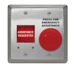
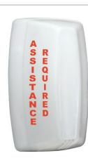
The CX-WEC10K2 Emergency Control Kit allows an individual to push the "PRESS FOR EMERGENCY ASSISTANCE" button to signal for help by illuminating the "Assistance Required" annunciator on the outside and the "Assistance Requested" annunciator on the inside of the location. At the same time activating the sounders built into both annunciators.
The kit also includes signage that states in the event of an emergency to press the button and an audible and visual signal will activate. The CX-WEC10K2 kit comes with the inside activation and annunciator built onto a double gang comboplate making installations quicker since one back box install is needed rather that two single gang boxes.
Note: CX-WEC10K2 Emergency Call System is OBC Regulation 368/13, Section 3.8.3.12 compliant.
2. OPERATION AT A GLANCE
When the "PRESS FOR EMERGENCY ASSISTANCE" button on the CM-AF540SO is pushed in it will change its normally open contact to a closed contact and activate the outside light and sounder (CM-AF141S0) to signal for help. The inside light and sounder (CM-AF540SO) will also be activated giving the individual inside confirmation that the action has taken place. Once the emergency has been attended to the red mushroom button on the CM-AF540SO can be pulled out to silence and reset the system.
Power
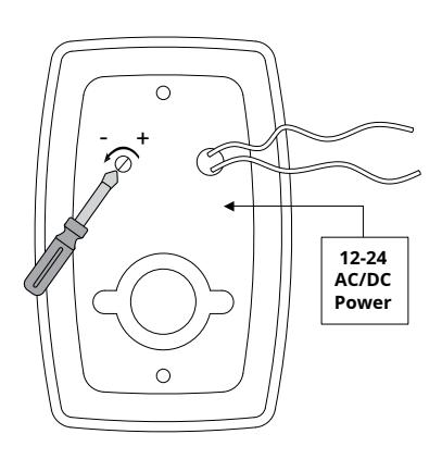
Both the CM-AF540SO and the CM-AF141SO can be powered with either 12/24 VAC/VDC.
Note: When the CX-WEC10K2 is integrated with a Camden Restroom Control Kit, VDC power must be used to prevent the door strike from buzzing.
Wiring the CX-WEC10K2 Emergency Control Kit
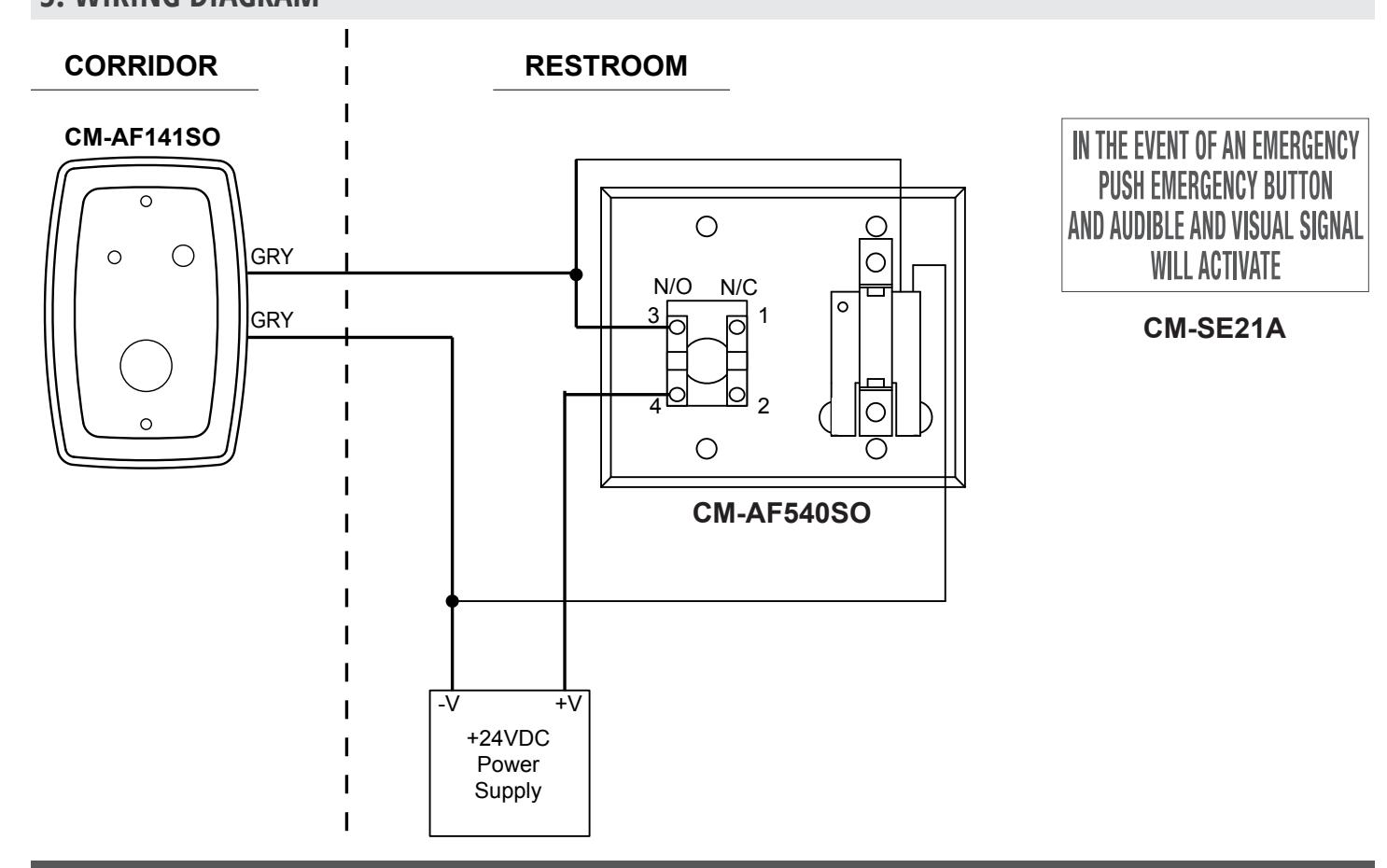
The inside and outside annunciators are wired in parallel to make them work at the same time when triggered. Take one of the black wires from the CM-AF540SO and one of the grey wires from the CM-AF141SO and tie them to the power supplies VDC ground (-).
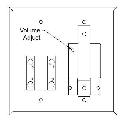
Next, take the remaining wires (black and grey) from these devices and wire it to the red mushrooms buttons normally open contact marked as terminal "3".
Lastly, wire the terminal marked as "4" to the positive (+) terminal of the VDC power supply.
Note: Some Door Operators provide excessive voltage levels above their posted values. Always measure voltages provided on both the VDC & VAC scales first before applying power to any part of the Emergency Control Kit.
3. INSTALLATION
Volume Adjust
Turn the volume adjust clockwise to increase the volume and counter clockwise to decrease the volume. Turn the volume adjust all the way counter clockwise to turn the sounder completely off.
CM-AF141SO
Mounts to a standard single gang electrical box.
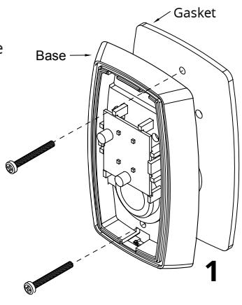
Step 1
Place the gasket (supplied) between the base unit and the electrical box. Use the 6-32 screws to fasten the base to the electrical box.
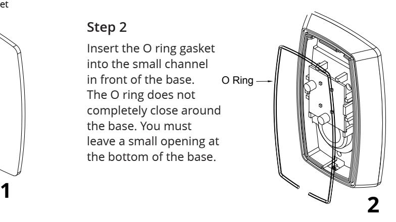
Step 2
Insert the O ring gasket into the small channel in front of the base. The O ring does not completely close around the base. You must leave a small opening at the bottom of the base.
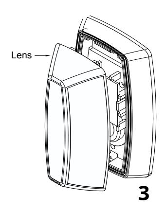
Step 3
Install the lens by inserting the large bottom tab first. The top tabs will snap in place with little effort.
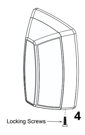
Step 4
Install the Phillips locking screw into the bottom of the base.
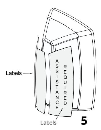
Step 5
Apply the labels as required to the lens.
Sound Volume Adjust
Using a small Phillips screwdriver, gently turn the volume adjustment counter clock wise to reduce the volume and clockwise to increase the volume.
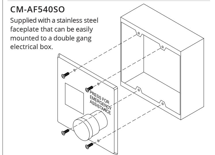
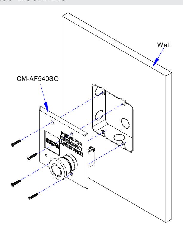
4. DOUBLE GANG CM-AF540SO MOUNTING
5. WIRING DIAGRAM
ORDERING INFORMATION FOR REPLACEMENT PARTS
| Item | Part Number | Description |
|---|---|---|
| 1 | CM-SE21A | English Solid white WEC Sign 6'' x 10-5/8'' |
| CM-AF141SO | ||
| 2 | 60-31A080 | LED PCB Board 18-30 VAC/VDC for CM-AF141SO |
| 3 | 60-42K003 | Styrene White Adapter Plate |
| 4 | 60-42C027-A | Plastic-Dome Lens with English Label ''Assistance Required'' |
| 5 | 60-42C027F-A | Plastic-Dome Lens with French Label |
| 6 | 60-42C027FE-A | Plastic-Dome Lens for With French & English Label |
| 7 | 60-81A012 | 6"x 2" Clear Lexan .010 Print Red English Label |
| 8 | 60-81A005 | 6"x 2" Clear Lexan .010 Print Red French Label |
| 9 | 60-81A004 | 6"x 2" Clear Lexan .010 Print Red Bilingual Label |
| CM-AF141SO Parts Kit | ||
| 10 | 60-34B075 |
6-32 x 3/4 Flat Head Phillips Zinc Plated Screw (2pcs)
#6 x 3/4" Steel Pan Head Phillips Zinc Screw (2 pcs) 5/16'' Phillips Rounded Head Screws (1 piece) Yellow/Grey Plastic Anchors 3/16" (2 pcs) Expanded Green PVC Anchors 10-24 Screw (2 pcs) Grey Plastic Wire Nut c/w Spring (2 pcs) Cut Cord (EPDM Durometer Cord CM-AF141SO) (1 piece) |
| CM-AF540SO | ||
| 11 | 60-66C000 | Normally Open Contact Block |
| 12 | 60-66C001 | Normally Close Contact Block |
| 13 | 60-66C002 | Normally Open & Normally Close Contact Block |
| CM-AF540SO Parts Kit | ||
| 14 | 60-34B083 |
6-32 x 3/4 Phillips Oval Head Stainless Steel Screw (4 pcs)
Snake Eye Tamper Proof Screw 6-32 X 3/4" (4 pcs) Key for Tamper Proof Screws (Snake Eye) (1 pc) Grey Plastic Wire Nut C/W Spring (2 pcs) |
Visit: www.camdencontrols.com