CX-WC17VR-PS Manual
Open the original PDF document
View PDFCX-WC17VR-PS SFRIFS RESTROOM KIT
Table 2.1 Different Modes for WC17VR-PS
| 0/1 |
, , , , |
O OLIVILO MEDIMODINI MII |
|
|---|---|---|---|
| INSTALLATION INSTRUCTIONS | |||
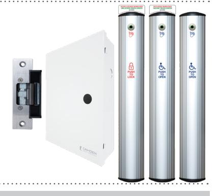
CX-WC17VR-PS SERIES RESTROOM KIT
INSTALLATION INSTRUCTIONS
1. GENERAL DESCRIPTION
The all-new Camden CX-WC17VR-PS Restroom Control Kit now comes with the CM-221 Hands-Free Switch, which uses active infrared microburst sensor technology and is designed to be used in ADA-compliant automatic door contro applications and access control. The CM-221 switch eliminates the spread of germs by avoiding physical contact and provides greater convenience when moving through the premises. For smooth operation, the CM-221 has an adjustable time delay of 0.5 to 20 seconds and an adjustable range of 2" to 8" (5cm to 20cm).
The CX-WC17VR-PS Restroom Control Kit is controlled by Camden's advanced relay logic controller, the CX-33. Camden's CX-33 is a 'state of the art' logic relay designed to support virtually any automatic door application.
The designation "PS" in the part number reflects that this kit now comes prewired in a metal enclosure with a power supply that is ready to accept all field
Operation at a Glance
The CX-WC17VR-PS has two modes: Mode 7 and Mode 8. The first mode refers to the "Normally Unlocked" condition, when the exterior PUSH to OPEN column switch is pressed or waved, it triggers the door operator to open the door. However, the second mode (Mode 8) refers to a "Normally Locked" condition, where entry to the restroom is accomplished by a Keyswitch, Keypad Prox Reader, or other secure means. The exterior PUSH TO OPEN Column switch may still be utilized, but in this mode it is to be wired in series with the limited access device mentioned above.
Inside the restroom, if the PUSH to LOCK column switch is pressed or waved, it keeps the door locked in either mode and disables the exterior PUSH to OPEN column switch. The LED light ring on the column switches turns red, indicating the restroom is occupied. The user can either press or wave PUSH to UNLOCK column switch as they exit the restroom. The LED light ring on the column switches turns green, indicating the restroom is now available to be used.
Note: While exiting, the user can also use a crash bar, paddle, or doorknob to unlock the door; in this case, the system will reset to its initial condition (mode 7 or mode 8), and the red light will turn green, allowing other users to use the restroom.
2. MODE SETTING
Mode Selection
Mode selection depends on the user requirements;
- If the user wants restroom to be unlocked during idle state, use Mode 7.
- If the user wants restroom to be locked during idle state, use Mode 8.
Note: The default mode for the CX-WC17PS is Mode 7 ( normally
There are three LED displays that will allow you to see what mode you have selected when advancing through the modes. To change the mode of the CX-WC17PS, simply press the MENU button once and use the UP button to advance to the desired mode.
Mode Editing
Camden builds in typical times for lock release and door operator activation, and is ready to use without changing any parameters. If you need to change the timing or delay for an output, it can be done by pressing the "MENU" button within the mode you selected. Once the option is selected, you can use the "UP or DOWN" buttons to select the timing needed. The first option (H & 1 flashing) will be how long relay 1 will be activated for (0-50 seconds). The second option (d & 1 flashing) will be how long to wait before activating relay 2 (0-15 seconds). The third option (H & 2 flashing) will be how long relay 2 will be activated for (0-50 seconds). The fourth option (d & 2 flashing) will be how long to wait before activating relay 3 (0-15 seconds). The fifth option (H & 3 flashing) will be how long relay 3 will be activated for (0-50 seconds). See the table 2.1
Factory Reset (Defaulting the CX-33)
To return the CX-33 back to its factory default settings, you will need to remove the power, then hold down the "MENU" button while powering up the CX-33. Once started, you will see the firmware version listed then a number "1" will be displayed. Reconnect your power and press the "MENU" button once, then use the "UP" or "DOWN" button to advance to the desired
For proper functionality, fully test the operation of the CX-WC11PS.
| Display ( M ) | Description ( Mode you are in ) | Parameters (1-15) |
|---|---|---|
| H, then 1 | Relay 1 Hold Time | 0.0 to 50 seconds |
| d, then 1 | Relay 2 Delay Time | 0.0 to 15 seconds |
| H, then 1 | Relay 2 Hold Time | 0.0 to 50 seconds |
| d, then 1 | Relay 3 Delay Time | Depends on Mode |
| H, then 1 | Relay 3 Hold Time | 0.0 to 50 seconds |
| d | Sets the display ON or OFF during operating mode | ON or OFF |
| А | Input delay on Activate. If other than 0.0 is selected, the input must be held in for the time period chosen before the CX-33 will activate. | 0.0 to 10 seconds |
| 1 | Set Dry Input 1 to activate on normally open or normally closed contact. | N/O OR N/C |
| 2 | Set Dry Input 2 to activate on normally open or normally closed contact. | N/O OR N/C |
| 3 | Set Dry Input 3 to activate on normally open or normally closed contact. | N/O OR N/C |
| 4 | Set Dry Input 4 to activate on normally open or normally closed contact. | N/O OR N/C |
| 5 | Set Dry Input 5 to activate on normally open or normally closed contact. | N/O OR N/C |
3. CM-7536VR COLUMN SWITCH INSTALLATION
Code Requirements: If installed according to these instructions the CM-7536VR Column switch will meet the requirements of the California Building Code (Section 1117B.6, Date: 2009), and Section 3.8.3.3.17(b) of the Ontario Building Code.
Installation Steps:
1. Take out pre-assembled unit from the box. To mount the switch, it is required to disassemble a few components. Firstly, remove two Phillips screw holding the top End Cap in place. Once both screws are removed, take out the cap. Then, carefully pull out actuation bar and place it aside so as to protect it from any surface damage.
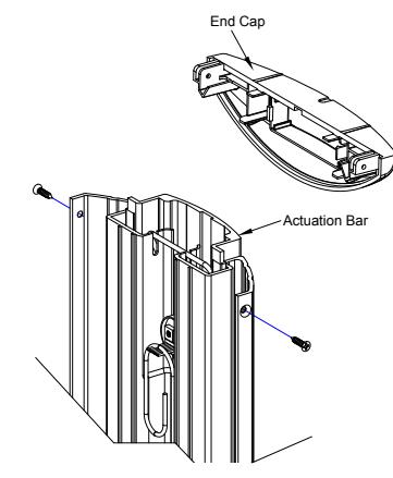
Figure 3.1 End Cap and Actuation Bar removal
2. Determine/Mark the optimum height and mounting location from the finished floor to mount the column switch. See the illustration below for the dimensions of the column switch.
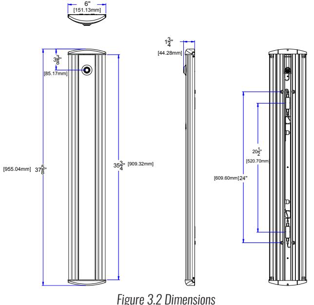
3. Center the touchless switch over the box for wire connection, while lining up the top edge with your mark (If installing through an in-wall electrical box), drill a Ø 0.25" hole for wire connection (If installing without an in-wall electrical box).
Page 1 of 9
Mounting without in-wall electrical box
included #14 screws.
screws (also provided).
End cap.
CM-7536VR Hands-Free Column™
4. CX-ED2079 'universal' electric strike installation
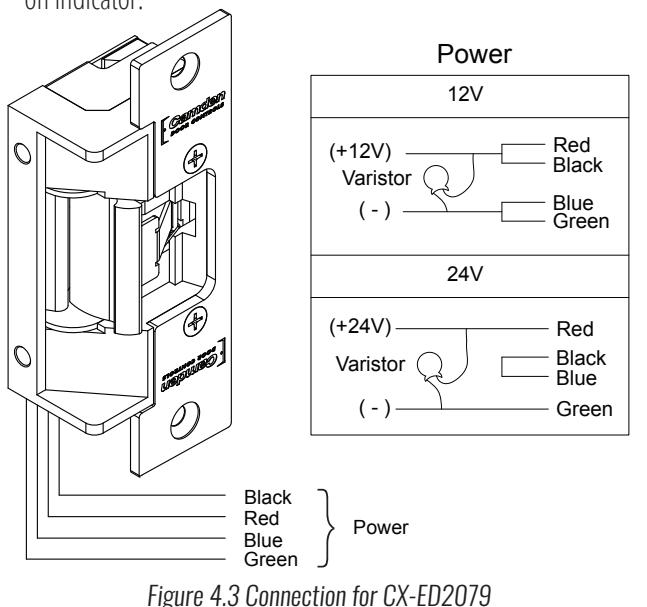
1. Firstly, verify that voltage required to operate Electric strike is compati- | 3. ble with supply voltage of the installation. POWER: Red/Black, Blue/Green (12 VDC)
Red, Black/Blue, Green (24 VDC) Red/Green (Sort Black, Blue)
2. Splice the strike wire with the supplied wire and make sure to attach provided varistor as described in connection section.
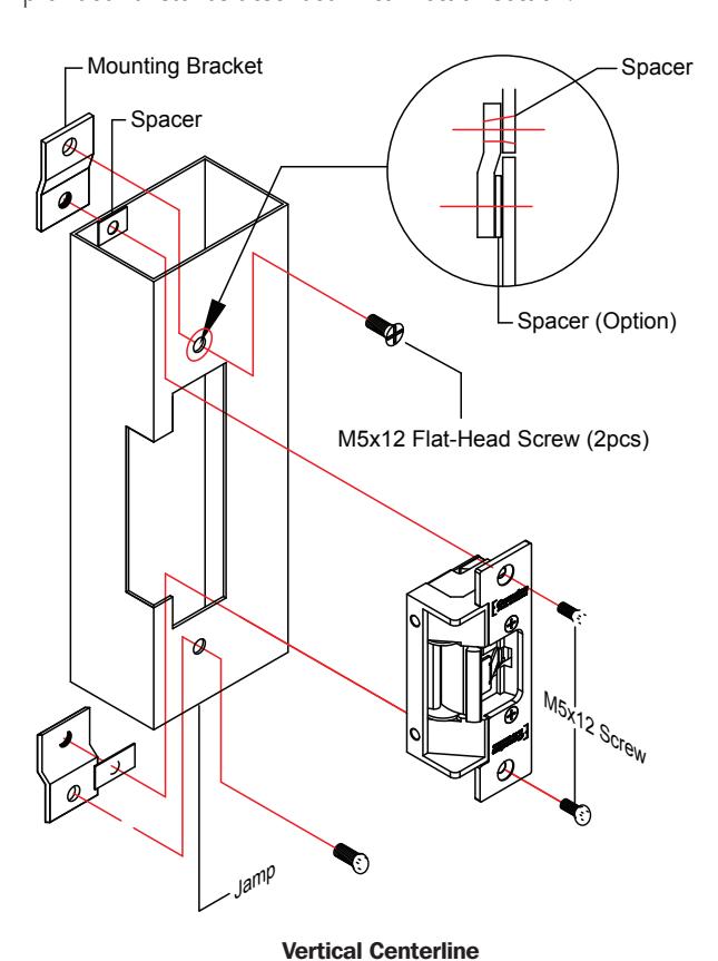
Figure 4.1 CX-ED2079 Strike Mounting
Note:
- The products are intended to be installed in accordance with the installation wiring diagram, mechanical assembly drawings provided with each product, the local authority having jurisdiction (AHJ) and the electric code, NFPA 70. When installed in fail secure mode, the local authority shall be consulted with the regards to the use of possible panic hardware to allow emergency exit from the secure
- The electric door strike shall be installed in such a way and in such a location so as to not impair the operation of an emergency exit device or panic hardware mounted on the door.
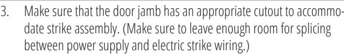
For a wooden door jamb, drill holes to install the strike and finally use supplied #12 x 1/2" machine screws to secure the strike.
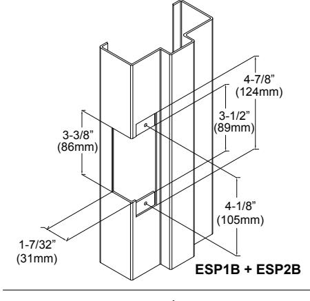
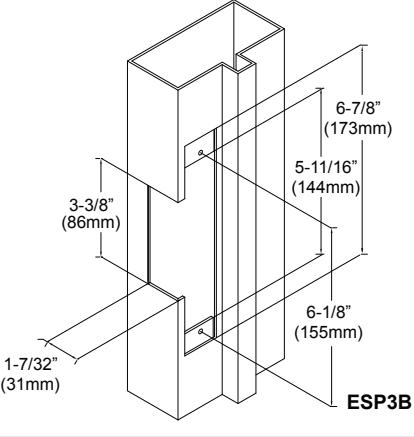
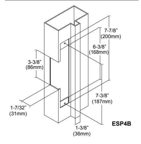
Figure 4.2 Mounting options for CX-ED2079
CONNECTIONS
IMPORTANT: Do not apply power to the unit until you have fully read the instructions and have made the required adjustments.
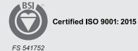
The CX-WC17VR-PS Restroom Control Kit comes with the CX-33PS: Advanced Logic Relay, Power Supply and Cabinet, which has a set of two terminal strips. Each strip has a clear label for wiring, and it is also pre-wired, which eliminates the need for a separate wiring manual for the termination point. However, later sections of this manual include detailed wiring diagrams for reference.
The left-side terminal strip is used to power CX-33PS, the PUSH to OPEN (both exterior and interior) column switches, PUSH to LOCK column switch, the door position switch, and the wet trigger. The right switch of the terminal is used to power the outputs to drive the strike (Relay 1), door operator (Relay 2), LED light (Relay 3), and provide VDC power for the door strike.
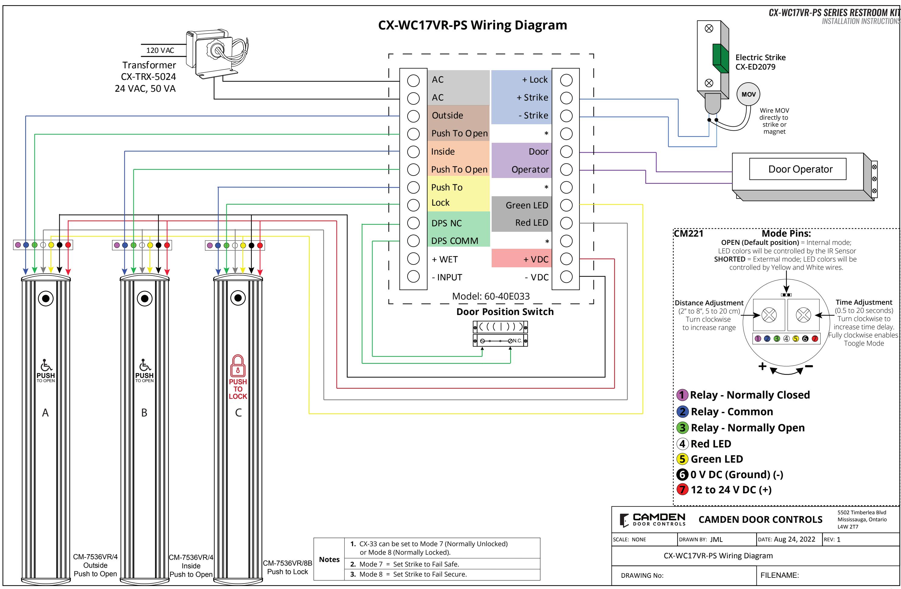
There are six wires from CM-221 needs to be connected with terminal strips:
Table 3.1 Wiring Description for CM221
| Table on Thing Decemption for Citizen | ||||
|---|---|---|---|---|
|
Wire Color
(from CM-221) |
Splicing With | To (CX-33PS) | ||
| Red wire | - | +V DC | ||
| Black wire | - | -V DC | ||
| Yellow wire | - | Green LED | ||
| White wire | - | Red LED | ||
| Green Wire | Top Switch wire | Inside/Outside Push to Open | ||
| Blue Wire | Top Switch wire | and Push to Lock | ||
| IMPORTANT: | ||||
The supplied CX-TRX-5024 transformer will have its secondary terminals wired to the terminals on the top of the left terminal strip marked as "AC". Next, wire the primary terminals to the AC feed to be used. Confirm your connections and apply power by turning on the electrical panel breaker.
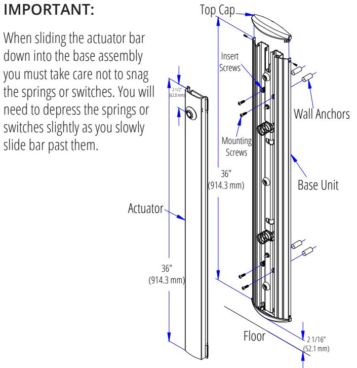
Figure 3.3 Mounting of Base Unit
Mounting with in-wall electrical box
Figure 3.3 Wall Mounting Options
4. Using a level tool, ensure the base unit is perfectly leveled and mark 4
mounting locations through the adjustable nylon inset screws onto the
wall surface (if mounting on drywall, use a pencil, and if mounting on
5. Drill the wall at the four marked locations and tap in the appropriate
wall plugs. We supply both drywall and concrete anchors for the
6. If mounting the Column Switch on an aluminium post or framing section, drill and tap four holes for 1/4"-20 stainless steel machine
7. Connect all the wires coming from the CX-33PS box to the CM-221
8. Secure the assembly with the provided mounting screw, and insert
actuation bar which was removed in step 1, and finally secure it with
concrete wall, use a narrow sharp object for marking).
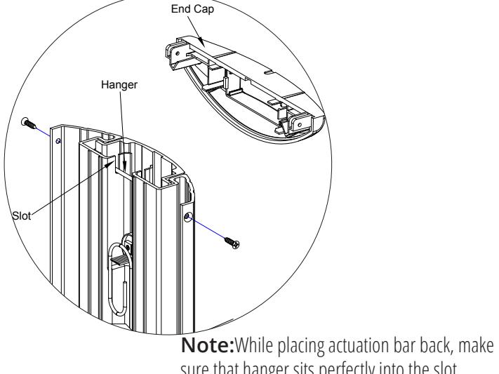
sure that hanger sits perfectly into the slot.
Page 4 of 9 Page 3 of 9
CONNECTIONS
A Varistor is provided to protect strikes from large volume spike. Connect varistor between the two input wires. Connection of the varistor varies based on input voltage. Please refer following table for more details;
| Dower | Varistor Connection | ||
|---|---|---|---|
| Power | +ve end | -ve end | |
| 12V | Red/Black | Blue/Green | |
| 24V | Red | Green | |
Note:
• For UL 294 and UL 1034 compliance, the door strikes are to be powered via a UL 294 or UL 603 class 2 power limited output from a control panel and/or power supply. In addition, when powered by AC or DC, the units must have a UL-regulated UL 294 or UL 603 power limited class 2 output rated at 12 or 24 volts, as well as an AC on indicator.
OPERATIONS
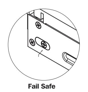
How to change from fail-safe to fail-secure and vice versa
- Loosen the screw as per the product diagram below.
- Rotate the set plate 180° and slide the plate until it is properly seated.
- Tighten the screw.

(9)
Fail Secure
Figure 4.4 Fail Safe and Fail Secure mechanism for CX-ED2079
ORDERING INFORMATION FOR PART REPLACEMENT
| ITEM | PART NUMBER | DESCRIPTION |
|---|---|---|
| 1 | 60-31A083 | Commutateur de capteur sans contact avec contrôle LED externe |
| 2 | 60-40E036 | Advanced Logic Control Relay And 2 Amp Power Supply In Pre-Wired Metal Cabinet |
| 3 | CX-MDA | Magnetic Door Contact |
| 4 | CX-ED2079 | Grade 2 Universal Electric Strike |
| 5 | CM-7536/4 | 36" Column "Push To Open" Switch |
| 6 | CM-7536/8B | 36" Column "Push To Lock" Switch |
CX-WC17VR-PS SERIES RESTROOM KIT
| INSTALLATION INSTRUCTIONS | |
|---|---|
| Notes: | |
| 1. | |
| 2. | |
| 3. | |
| 4. | |
| 5. | |
| 6. | |
| 7. | |
| 8. | |
| 9. | |
| 10. | |
| 11. | |
| 12. | |
| 13. | |
| 14. | |
| 15. | |
| 16. | |
| 17. | |
| 18. | |
| 19. | |
| 20. | |
| 21. | |
| 22. | |
| 23. | |
| 24. | |
| 25. | |
| 26. | |
Questions? Call us toll-free at 1-877-226-3369 or technical support 905-366-3377 (ext. 505)

Call: 1.877.226.3369 / 905.366.3377
File: WC17VR-PS.indd Rev.: March 3<sup>rd</sup> 2023 Part No: 40-82B271VR
CX-WC17VR-PS SERIES RESTROOM KIT
INSTALLATION INSTRUCTIONS
Spec Ref # CXWC17VR-PS
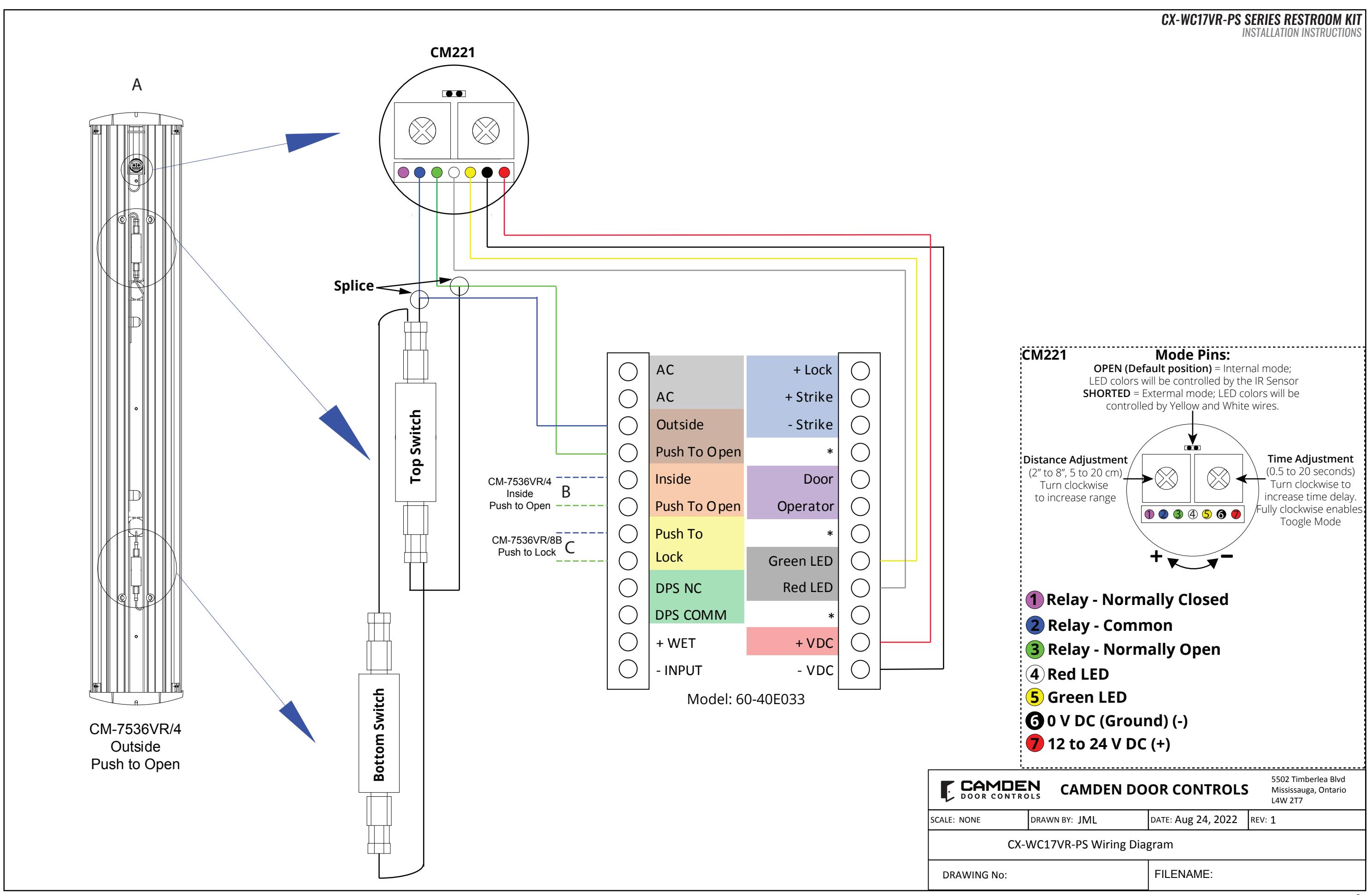
CX-WC17VR-PS EQUIPMENT PACKAGE:
- 1 CX-33PS (60-40E033) POWER SUPPLY CABINET WITH CX-TRX-4024 40VA, 24 VAC TRANSFORMER
- 2 CM-7536VR/4 36" COLUMN "WHEELCHAIR" SYMBOL AND "PUSH TO OPEN" GRAPHICS WITH MOUNTED VALUEWAVE™ HANDS FREE SWITCH AND SIGN
- 3 CM-7536VR/8B 36" COLUMN "LOCK" SYMBOL AND "PUSH TO LOCK" GRAPHICS SWITCH WITH MOUNTED VALUEWAVE™ HANDS FREE SWITCH AND SIGN
- 4 CX-MDA MAGNETIC DOOR CONTACT
- 5 CX-ED2079 GRADE2 UNIVERSAL ELECTRIC STRIKE
ADDITIONAL PARTS REQUIRED BUT NOT INCLUDED WITH THE CX-WC17VR-PS
6 DOOR OPERATOR - SUPPLIED BY OTHERS
SYSTEM OPERATION
CX-WC17VR-PS OPERATION:
- THE DOOR IS NORMALLY CLOSED AND UNLOCKED.
- B. OPERATING THE EXTERIOR ACTIVE SWITCH OPENS THE
- C. ONCE INSIDE AND THE DOOR IS CLOSED, PRESSING THE COLUMN SWITCH WITH THE 'LOCK' SYMBOL AND 'PUSH TO LOCK' LOCKS THE DOOR, THE LIGHT RING AROUND THE VALUEWAVE™ HANDS FREE SWITCH TURNS FROM GREEN TO RED.
- D. PRESSING THE INTERIOR 'WHEELCHAIR' SYMBOL AND 'PUSH TO OPEN' COLUMN SWITCH UNLOCKS THE DOOR, DEACTIVATES AND RESETS THE SYSTEM
- E. IF THE DOOR IS OPENED MANUALLY TO EXIT THE RESTROOM, THE OVERHEAD MAGNETIC CONTACT SWITCH RESETS THE SYSTEM.
WIRE SPECIFICATION A 2 x 18 AWG B 2 x 22 AWG C 6 x 20 AWG