CX-WC14AXFM-PS System Manual
Open the original PDF document
View PDFINSTALLATION INSTRUCTIONS
WC14PS SERIES RESTROOM CONTROL
Electrified Locks, Relays and Timers
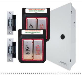
WC14PS 2 Door Restroom Control System
INSTALLATION INSTRUCTIONS
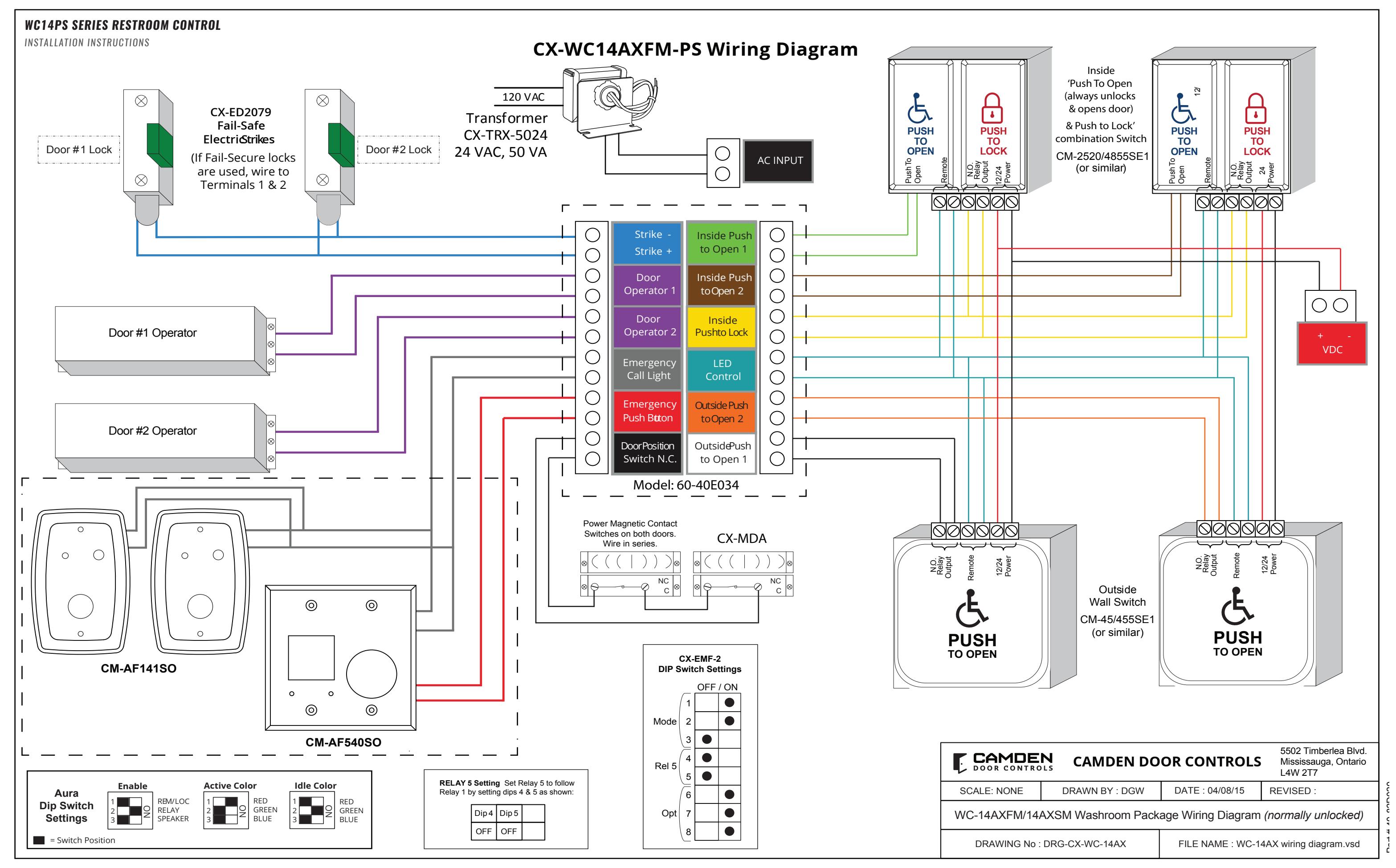
1. GENERAL DESCRIPTION
The CX-WC14PS is a two-door shared Restroom kit that allows patrons to enter, lock and exit through either of the two doors. It also provides visual notification that the restroom is either occupied or vacant.
The CX-WC14PS Series of Restroom Control Kits are controlled by Camden's advanced relay logic controller CX-EMF-2.
The mode for the CX-WC14PS is a normally unlocked restroom. This Restroom Control Kit will provide the ability to physically open the door, then allow the patron to lock the door once inside. By pushing either of the two PUSH TO LOCK buttons on the inside of the Restroom, the CX-EMF-2 will change the coloring of the inside & outside PUSH TO OPEN buttons from green to red, displaying that the Restroom is in use. When either of the inside PUSH TO OPEN buttons are pressed, it will unlock the door, then physically open the door and change the coloring of the inside & outside PUSH TO OPEN buttons back to green, displaying that the Restroom is now vacant. The locked Restroom can also be unlocked by using the crash bar, paddle or turning the knob set to open the door contact circuit, and resetting the CX-EMF-2 back to the unlocked position.
The CX-WC14PS Series of Restroom Control Kits kit uses Camden's trademark Aura boards. The Aura circuit board is installed behind the outside PUSH TO OPEN buttons and behind both of the PUSH TO LOCK/PUSH TO OPEN (CM-2520) combo buttons on the inside of the room which will make them easily seen by patrons at a distance.
2. INSTALLATION
Operation at a Glance
When the exterior PUSH TO OPEN button is pressed, it will trigger the PBTN input on its Aura board causing its N.O. relay contact to send a momentary closure to the Outside PUSH TO OPEN terminal on the CX-WC14PS allowing the door to swing open. When either of the interior PUSH TO LOCK buttons is pressed, it will trigger the PBTN input on its Aura board causing its N.O. relay contact to send a momentary closure to Inside PUSH TO LOCK terminal causing the CX-WC14PS to lock the Restroom and switch the Aura colors from green to red.
Both inside PUSH TO OPEN buttons are wired to Inside PUSH TO OPEN terminal on the CX-WC14PS. When either one is pressed the Restroom will unlock and the door will swing open.
The Restroom can also be unlocked by opening the door from the inside which will break the door contact circuit causing the CX-WC14PS to reset and unlock the door. The Aura's will switch back to green signalling the Restroom is now vacant.
Emergency Call System Option
If the emergency PRESS FOR ASSISTANCE button (CM-450R/12) is pressed on the inside of the Restroom, it will not only activate the inside annunciator (CM-AF501SO) letting the patron know that they have requested assistance, but will also activate both dome light/sounders (CM-AF141SO) on the exterior above each door this provides an audible and visual notification that an individual is in need of assistance at this location.
Resetting the annunciators on both the inside and outside of the Restroom is simply done by pulling out the CM-450R/12 PRESS FOR ASSISTANCE button, which will turn off the sounders and dome lights.
Additional Options:
- 1. Unlock the door and send a signal for assistance.
- 2. Unlock and open the door and send a signal for assistance.
- 3. The output can be either maintained or pulsed (a pulsed light will attract more attention).
- 4. CX-EMF-2 will reset itself after 15 minutes and unlock the door.
There is one DIP switch bank with 8 switches.
Dip switch 1, 2 & 3 sets the mode. Unsecured Restroom: 1 ON, 2 & 3 OFF. Secured Restroom: 1 & 3 OFF, 2 ON. Dip switch 4 & 5 sets Relay 5 to follow Relay 1. Provides a secondary function every time Relay 1 is triggered. Dip switch 6 ON sets the door to unlock and open when the panic button is pressed. Set to OFF only unlocks the door Dip switch 7 ON sets the door to unlock after 15 minutes.
OFF disables this feature. Dip switch 8 in Unsecured mode is not used. Dip switch 8 -Secured mode, OFF can have a keypad (or any other device) unlock and open the door.
-Secured mode, ON can have a keypad (or any other device) unlock to door. The exterior PUSH TO OPEN button will open the door when pressed.
Mounting
IMPORTANT: Do not apply power to the unit until you have fully read the instructions and have made the required adjustments.
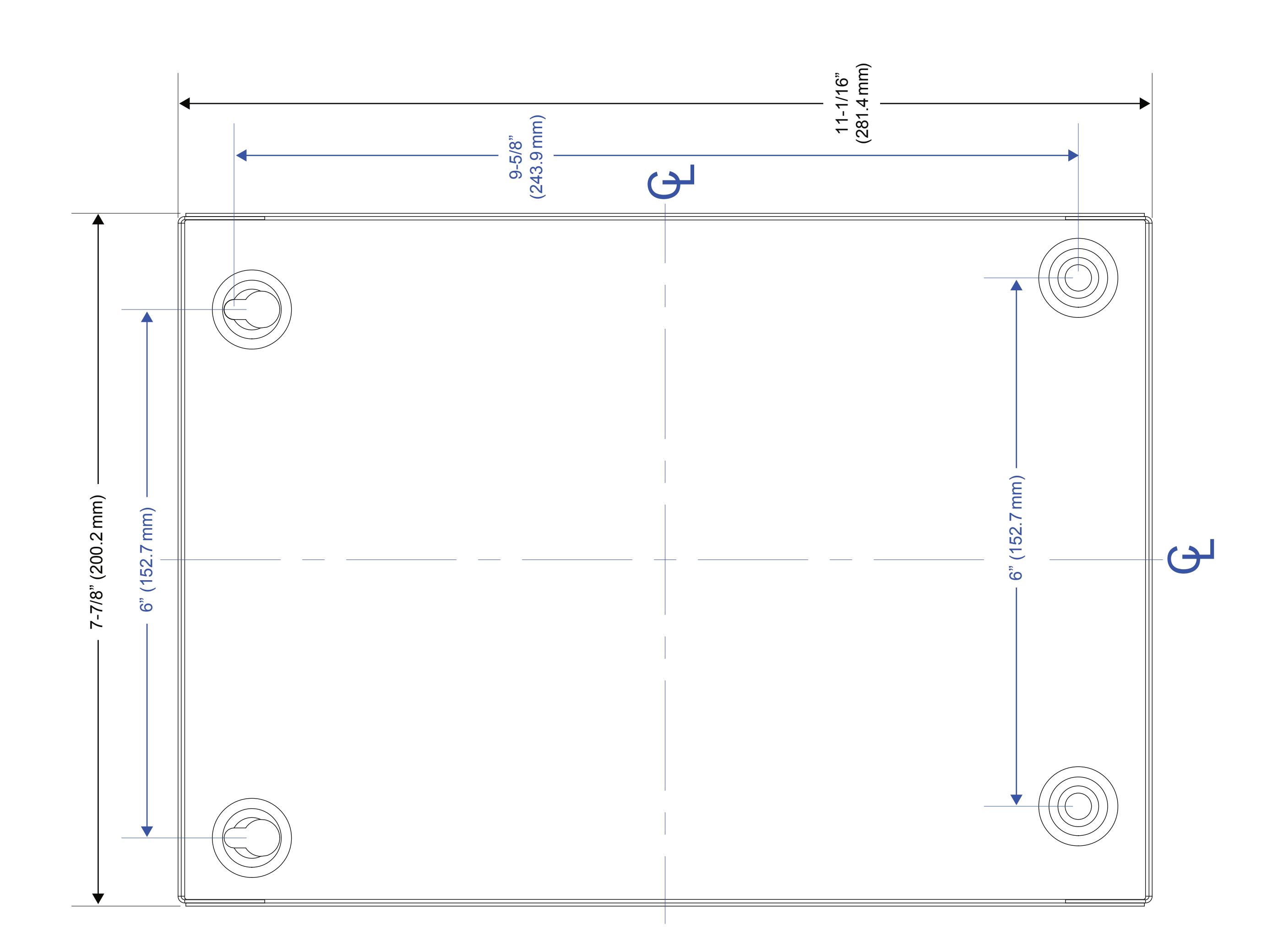
The CX-WC14PS cabinet should be mounted in a clean dry location out of direct contact with the elements.
Wiring the CX-WC14PS Series Restroom Control Kit is as follows:
CX-WC14PS comes from Camden with the CX-EMF-2 pre-wired to a labeled set of two terminal strips. This makes wiring the field hardware easier since the wiring manual will no longer need to be directly referenced for termination points.
A complete wiring diagram is adhered to the inside of the door to provide a wiring layout as a reference when wiring the field devices to the kit.
There are two labeled terminal strips wired to the CX-EMF-2. The left strip is used for strike power (Relay 1), door operator 1 (Relay 2) and door operator 2 (Relay 3), emergency call light (Relay 4), emergency push button (Input 3), and the door position switch (Input 6). The right strip is for both the Inside PUSH TO OPEN buttons for door 1 & 2, the Inside PUSH TO LOCK, LED control (Aura boards Relay 5) and both Outside PUSH TO OPEN buttons for door 1 & 2.
The two inside PUSH TO OPEN buttons will be wired in parallel to the INSIDE PUSH TO OPEN terminal on the CX-WC14PS. The two PUSH TO LOCK buttons will be wired in parallel to the PUSH TO LOCK terminal on the CX-WC14PS. All four Aura boards (two on the outside and two on the inside) will have their REM inputs wired in parallel and will go to the CX-WC14PS terminals marked as LED CONTROL.
Once all field devices are wired to the CX-WC14PS then AC power can be wired in.
IMPORTANT: Confirm the electrical panels breaker you are going to be using is currently off. Do not wire the primary terminals of the transformer until the secondary terminals are connected first.
The supplied CX-TRX-5024 transformer will have its secondary terminals wired to the top right of the enclosure to the terminals marked as "AC" (with two sinewaves).
Next, wire the primary terminals to the AC feed to be used. Confirm your connections and apply power by turning on the breaker on the electrical panel.
Selecting a Mode
The CX-WC14PS can accommodate Restroom applications that are either normally locked or unlocked upon approach.
The default mode for the CX-WC14PS is normally unlocked. Both Fail-Locked and Fail-Unlocked strikes are wired to the common and normally open poles on the relay.
The dip switch bank with eight switches will let you select this mode. To change the mode of the CX-WC14PS, simply slide to the "ON" position the required switches. In this case only switches 1 & 2 will be moved to the "ON" position.
Note: Anytime any of the switches are moved, the CX-EMF-2 must have its power recycled (remove the two-pin terminal block for power for at least 2 seconds).
Editing the Settings for a Mode
Although the modes are selectable by changing the dip switch configuration it might be necessary to adjust the timing between relays triggering. This is done by adjusting the five potentiometers at the top of the CX-EMF-2.
In this application, you will use Potentiometers 2 to 5.
Potentiometer 1 - has no effect
Potentiometer 2 - Operator Delay-on-activation (how
Potentiometer 3 - Operator Delay-on-release Potentiometer 4 - Panic Relay (#4) ON time Potentiometer 5 - Panic Relay (#4) OFF time
Note: If Potentiometer 5 is turned to zero, relay will be on steady
Fully test the operation of the CX-WC14PS for proper functionality.
Page 2 of 11 Page 1 of 11
SURFACE MOUNT RESTROOM INSTALLATION
- 1. Place the white vinyl sign behind the surface aura enclosure and place them against the mounting wall.
- 2. Use the #10 x 1'' pan head screws with the green pvc anchors provided to hold the white vinyl sign and the aura enclosure against the wall .
Note: White vinyl sign does not come with the CM-45/4 - 4 1/2" 'Push To Open'.
- 3. Place all the square rubber pads inside the flush aura enclosure. Insert the aura board inside the flush aura enclosure, making sure the screw holes on the aura board align with the screw holes inside the surface aura enclosure. Use the #6 x 3/8" self-tapping screws to tighten Aura board in place.
- 4. Place the Aura insert inside the surface aura enclosure, making sure the mounting screw holes on the aura insert and the surface aura enclosure align.
FOR CM-45/454SE1, CM-45/854SE1 & CM-45/4 SWITCHES
- a. Use the 6-32 hex head screws to tighten the aura insert slightly.
- b. Fit in the assembled CM-45/4 by locating the screws with the holes on the backplate.
- c. Fit the hex key through the hole on the face plate and completely tighten the 6-32 screws in place.
FOR CM-2520-4854SE1 COMBO SWITCH
- a. Fit the plastic spacer inside the aura insert
- b. Place the combo switch Inside the aura insert, making sure the mounting holes on the aura and on the back plate align
- c. Use the 6-32 Phillips screws to tighten in place.
- 5. Apply the label to the black vinyl as required.
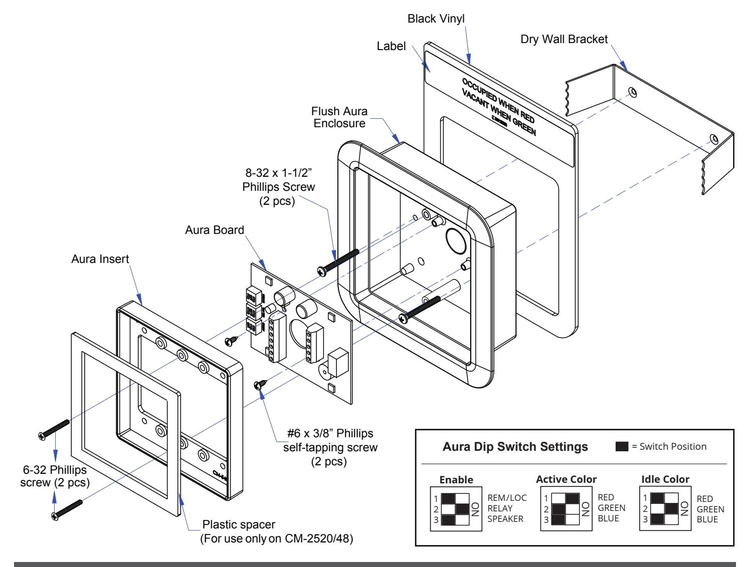
Surface Aura Enclosure #10 x 1" Pan Head Screw (4 pcs) #6 x 3/8" Phillips self-tapping screw (2 pcs) 5/8" x 5/8" Square Rubber Pad (4 pcs) 6-32 Phillips screw (2 pcs) Aura Board Plastic spacer (For use only on CM-2520/48) Aura Dip Switch Settings 1 REM/LOC RELAY SPEAKER 2 3 Enable ON 1 RED GREEN BLUE RED GREEN BLUE 2 3 Active Color ON 1 2 3 Idle Color ON = Switch Position White Vinyl Label Aura Insert
FLUSH MOUNT RESTROOM INSTALLATION
- 1. Prepare the cut-out for the unit and fit in the dry wall bracket.
- 2. Slide in the black vinyl behind the flush aura enclosure and fit them inside the dry wall bracket.
Note: Black vinyl does not come with the CM-45/4 - 4 1/2" 'Push To Open'.
- 3. Ensure the two mounting holes on the bracket and the Flush aura enclosure align. Use the 8-32 phillips screws to completely tighten in place.
- 4. Place the aura board inside the flush aura enclosure, making sure the screw holes on the aura board align with the screw holes inside the Flush aura enclosure. Use the #6 x 3/8" self-tapping screws to tighten Aura board in place.
- 5. Place the Aura insert inside the Flush aura enclosure, making sure the mounting screw holes on the aura insert and the flush aura enclosure align.
FOR CM-45/455SE1, CM-45/855SE1 & CM-45/4 SWITCHES
- a. Use the 6-32 hex head screws to tighten the aura insert slightly.
- b. Fit in the assembled Push plate by locating the screws with the holes on the backplate.
- c. Fit the hex key through the hole on the face plate and completely tighten the 6-32 screws in place.
FOR CM-2520-4855SE1 COMBO SWITCH
- a. Fit the plastic spacer inside the aura insert
- b. Place the combo switch Inside the aura insert, making sure the mounting holes on the aura and on the back plate align.
- c. Use the 6-32 Phillips screws to tighten in place
- 7. Apply the label to the black vinyl as required.
Page 4 of 11 Page 3 of 11
4. Installation
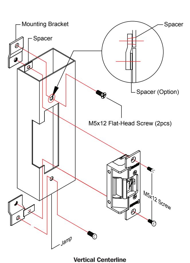
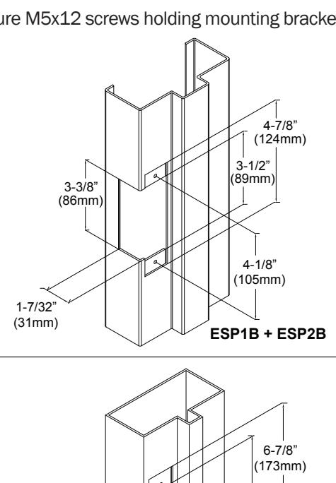
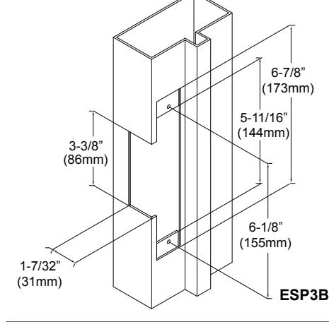
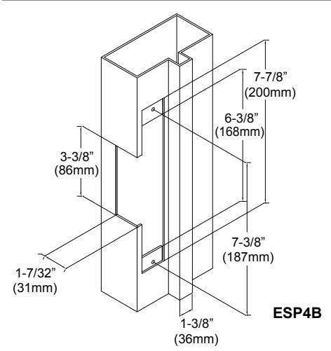
CX-ED2079 'UNIVERSAL' ELECTRIC STRIKE INSTALLATION CONNECTIONS OPERATIONS
- 1. Prepare the door jamb as per the appropriate drawing.
- 2. Install mounting brackets to jamb using M5x12 screws and pressed metal nuts. Do not tighten.
- 3. Spacers are used to assure flush final assembly of faceplate into jamb. Add one of more spacers between jamb and mounting bracket when face plate extends beyond the jamb. When the faceplate sits inside the jamb, spacers must be added between the mounting
Note: The products are intended to be installed in accordance with the installation wiring diagram, mechanical assembly drawings provided with each product, the local authority having jurisdiction (AHJ) and the National Electric Code, NFPA 70. When installed in fail secure mode, the local authority shall be consulted with regard to the use of possible panic hardware to allow emergency exit from the secure area.
The electric door strike shall be installed in such a way and in such a location so as to not impair the operation of an emergency exit device or panic hardware mounted on the door.
- bracket & the lip bracket. Make sure clearance hole in spacer aligns with hole in mounting bracket.
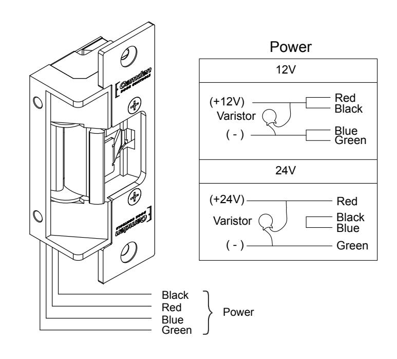
- 4. Connect wires coming from the low voltage side of the transformer to wires (black) from strike.
- 5. Install electric strike jamb by attaching with # 10-32 screws and lockwashers.
- 6. Secure M5x12 screws holding mounting brackets to jamb.
POWER 12VDC
Red/Black: +12V Blue/Green: Ground
24VDC
Red: +24V Black/Blue: - Green: Ground
A varistor is provided to protect strike from spikes. Connect varistor between input wires.
Note: For UL 294 / UL 1034 compliance the door strikes are to be powered via a UL 294/ UL 603 class 2 power limited output from a control panel and/or power supply. Furthermore, when powered by AC/DC, the units shall use a UL regulated UL 294/ UL 603 power limited class 2 output rated 12/24V with AC on indicator.
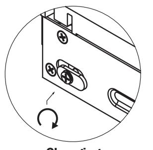
How to modify fail-safe to fail-secure or vice versa.
- 1. Loosen the screw as per the product diagram below.
- 2. Rotate the set plate 180° and slide the plate until it is properly seated.
- 3. Tighten the screw.
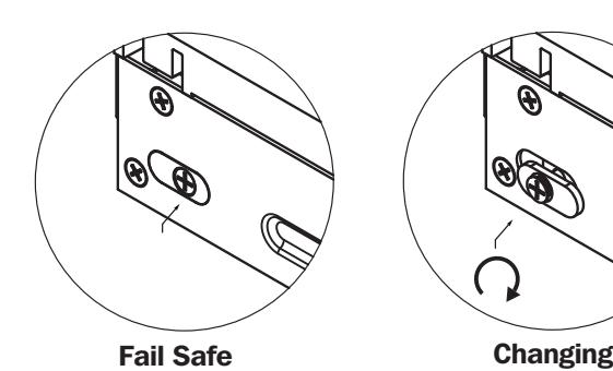
Fail Secure
Page 6 of 11 Page 5 of 11
RESTROOM SIGNAGE
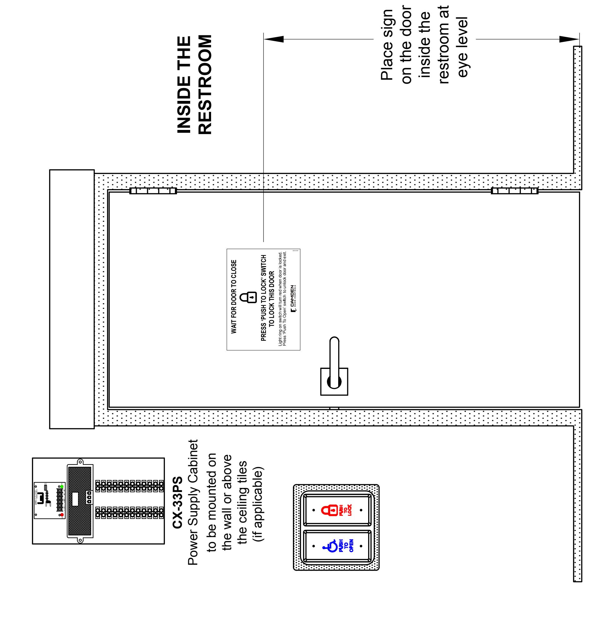
INSTALLATION INSTRUCTIONS
WC14PS SERIES RESTROOM CONTROL
INSTALLATION INSTRUCTIONS
ORDERING INFORMATION FOR REPLACEMENT PARTS Notes :
| Item | Part Number | Description |
|---|---|---|
| 1 | 60-31A041 | Blue/Red/Green Aura PC Board |
| 2 | 60-42C012 | Square Aura Insert |
| 3 | 60-40E033 | Advanced Logic Control Relay and 2 Amp Power Supply in pre-wired metal cabinet |
| 4 | CX-MDA | Magnetic Door Contact |
| 5 | 60-42C019 |
Mounting Box, Flush Aura Enclosure.
Flame/Impact Resistant Black Polymer (ABS) 6-1/2"W X 6-1/2"H X 2"D |
| 6 | 60-42C010 |
Mounting Box, Surface Aura Enclosure.
Flame/Impact Resistant Black Polymer (ABS) 5-1/4"W X 5-1/4"H X 2"D |
| 7 | 60-81C021 |
English Self-Adhesive Vinyl Sign
''WAIT FOR DOOR TO CLOSE'' |
| Black Vinyl & Sign for Flush Aura Enclosure | ||
| 8 | CM-SFE1 |
Black Vinyl & English Label
''DOOR LOCKED WHEN RED/UNLOCKED WHEN GREEN'' & ''OCCUPIED WHEN RED/VACANT WHEN GREEN'' |
| 9 | CM-SFF1 |
Black Vinyl & French Label ''OCCUPÉ/LIBRE'' &
''PORTE BARRÉE/PORTE DÉBARRÉE'' |
| 10 | CM-SFFE1 |
Black Vinyl & English Label
''DOOR LOCKED WHEN RED/UNLOCKED WHEN GREEN'' & ''OCCUPIED WHEN RED/VACANT WHEN GREEN'' Black Vinyl & 2-sided French Label ''OCCUPÉ/LIBRE'' & ''PORTE BARRÉE/PORTE DÉBARRÉE'' |
| White Vinyl & Sign for Surface Aura Enclosure Installed | ||
| 11 | CM-SE1 |
White Vinyl & English Label
''DOOR LOCKED WHEN RED/UNLOCKED WHEN GREEN'' & ''OCCUPIED WHEN RED/VACANT WHEN GREEN'' |
| 12 | CM-SF1 |
White Vinyl & French Label ''OCCUPÉ/LIBRE'' &
''PORTE BARRÉE/PORTE DÉBARRÉE'' |
| 13 | CM-SEFE1 |
White Vinyl & English Label
''DOOR LOCKED WHEN RED/UNLOCKED WHEN GREEN'' & ''OCCUPIED WHEN RED/VACANT WHEN GREEN'' White Vinyl & 2-sided French Label ''OCCUPÉ/LIBRE'' & ''PORTE BARRÉE/PORTE DÉBARRÉE |
| 1. | |
|---|---|
| 2. | |
| 3. | |
| 4. | |
| 5. | |
| 6. | |
| 7. | |
| 8. | |
| 9. | |
| 10. | |
| 11. | |
| 12. | |
| 13. | |
| 14. | |
| 15. | |
| 16. | |
| 17. | |
| 18. | |
| 19. | |
| 20. | |
| 21. | |
| 22. | |
| 23. | |
| 24. | |
| 25. | |
| 26. | |
Questions? Call us toll-free at 1-877-226-3369 or technical support 905-366-3377 (ext. 505)

Call: 1.877.226.3369 / 905.366.3377 Visit: www.camdencontrols.com
File: WC14PS Restroom Controls Manual.indd Rev.: May 19, 2020 Part No: 40-82B246
CABINET BASE