CX-WC11ASM-PS System Manual
Open the original PDF document
View PDF


WC11PS Series Restroom Control
INSTALLATION INSTRUCTIONS
1. GENERAL DESCRIPTION
The CX-WC11PS Restroom Control Kit allows access in and out of a restroom with the ability to secure the door once inside. The Kit also provides annunciation by including an Occupied light. The designation of "PS" in the part number reflects that this kit now comes pre-wired in a metal enclosure with a power supply which is ready to accept all field wiring.
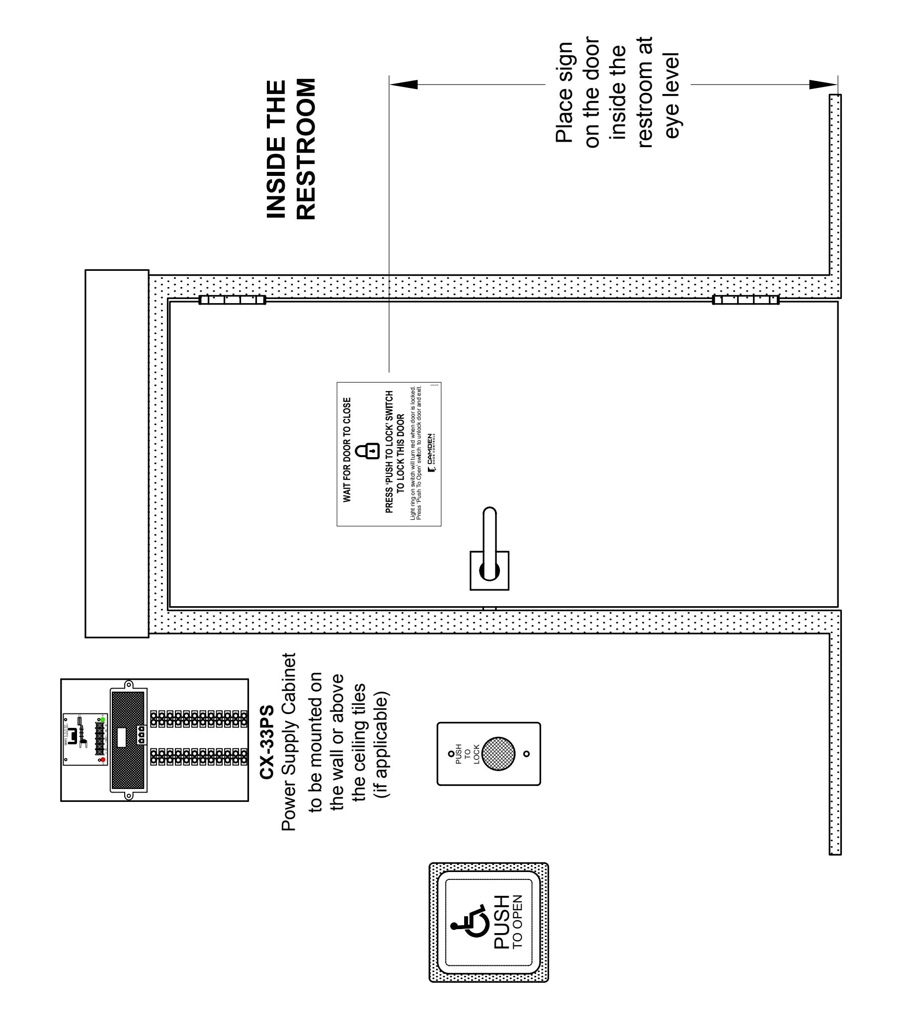
The CX-WC11PS Restroom Control Kit is controlled by Camden's advanced relay logic controller part numbered as the CX-33. The CX-WC11PS has two modes. One is Mode 7 for a normally unlocked restroom and the other is Mode 8 for a normally locked restroom. In Mode 7 when the exterior PUSH to OPEN button is pressed it will trigger the door operator to open the door. In Mode 8 when the exterior PUSH to OPEN button is pressed it will unlock the strike and trigger the door operator to open the door. Once in the restroom and the PUSH to LOCK button is pressed it will keep the door locked in either mode and disable the exterior PUSH to OPEN button, as well as, providing annunciation with an Occupied light. When exiting the restroom, you can either press the inside PUSH to OPEN button to unlock the door and open the door or you can push the crash bar, paddle or turn the knobset to break the door contact circuit which will also unlock the door and reset the system. The Occupied light will turn off signaling the restroom is available.
2. INSTALLATION
Operation at a Glance
When the exterior PUSH TO OPEN button is pressed it will send a momentary closure to the outside PUSH TO OPEN terminal on the CX-WC11PS allowing the door to swing open. When the interior PUSH TO LOCK button is pressed it will send a momentary closure to the to inside PUSH TO LOCK terminal on the CX-WC11PS causing it to lock the restroom and turn on the Occupied light. When the inside PUSH TO OPEN button is pressed it will send a momentary closure to the inside PUSH TO OPEN terminal on the CX-WC11PS causing it to unlock the door and open it. The Occupied light will now turn off signalling the restroom is now vacant. The restroom can also be unlocked by opening the door from the inside which will break the door contact circuit causing the CX-WC11PS to reset and unlock the door.
Mounting
IMPORTANT: Do not apply power to the unit until you have fully read the instructions and have made the required adjustments.
The CX-WC11PS cabinet should be mounted in a clean dry location out of direct contact with the elements.
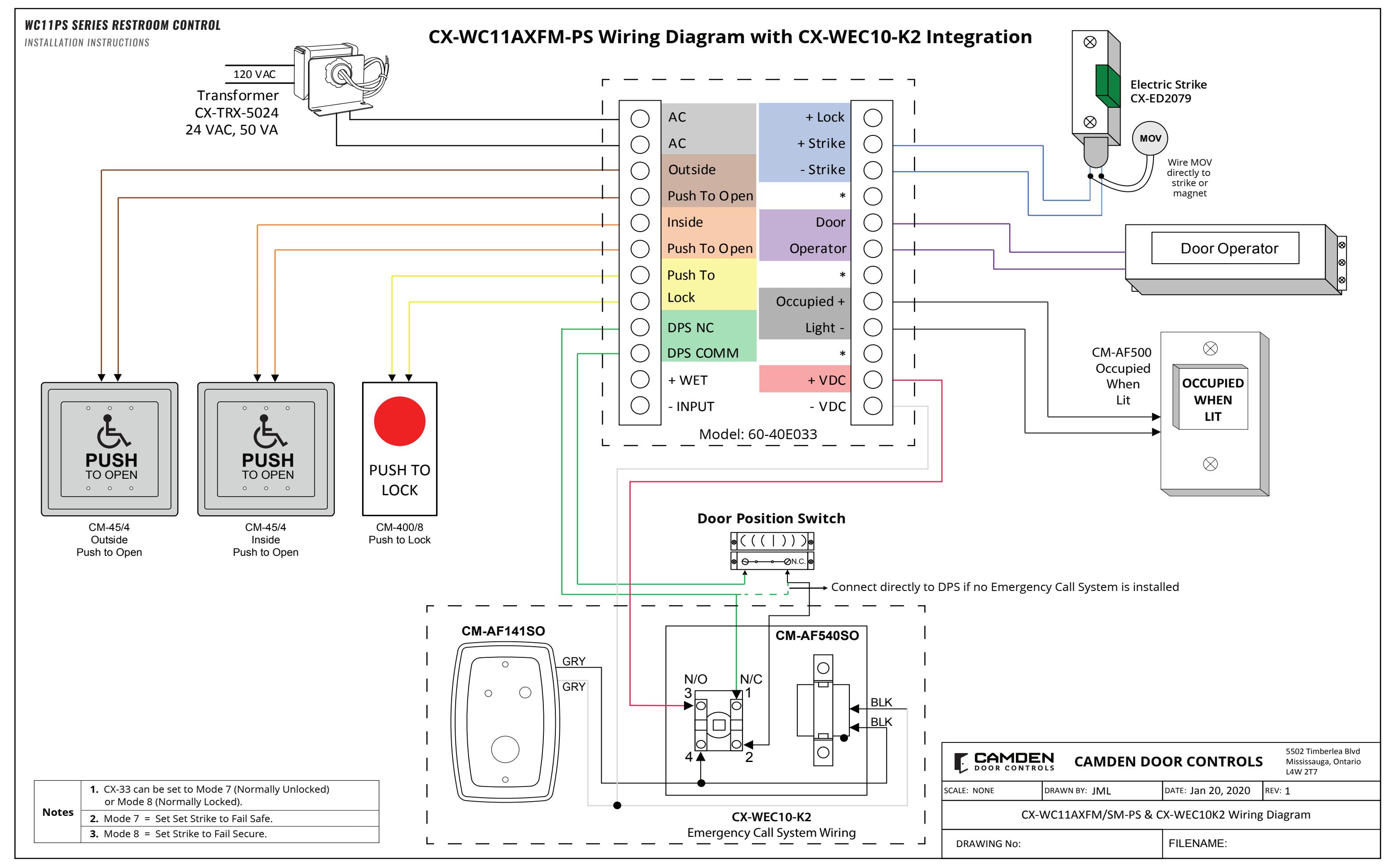
Wiring the CX-WC11PS Series Restroom Control Kit is as follows:
The CX-WC11PS comes from Camden with the CX-33 pre-wired to a labeled set of two terminal strips. This will make the wiring of the push buttons easier since the wiring manual will no longer need to be directly referenced for termination points. A complete wiring diagram is adhered to the inside of the door to provide a layout of the wiring as a reference when wiring the field devices to the kit.
There are two terminal strips that mirror the locations on the CX-33. The left strip is used for power to the CX-33, the PUSH TO OPEN and PUSH TO LOCK buttons, the door position switch, and the Wet trigger. The right strip is for the outputs to drive the strike (Relay 1), door operator (Relay 2), Occupied light (Relay3), and to provide VDC power for the door strike.
Once all field devices are wired to the CX-WC11PS then AC power can be wired in.
IMPORTANT: Confirm the electrical panels breaker you are going to be using is currently off. Do not wire the primary terminals of the transformer until the secondary terminals are connected first.
The supplied CX-TRX-5024 transformer will have its secondary terminals wired to the terminals on the top of the left terminal strip marked as "AC". Next, wire the primary terminals to the AC feed to be used. Confirm your connections and apply power by turning on the electrical panels breaker.
Selecting a Mode
The CX-WC11PS has two restroom applications built in (Mode 7 & 8). The default mode for the CX-WC11PS is Mode 7 (normally unlocked).
Determining which mode is correct for you will be based on whether the restroom will be normally unlocked (Mode 7) or normally locked (Mode 8).
There are three LED displays that will allow you to see what mode you have selected when advancing through the modes. To change the mode of the CX-WC11PS simply press the MENU button once and use the UP button to advance to the desired mode.
Editing the Settings for a Mode
Camden builds in typical times for lock release and door operator activation and is ready to use without changing any parameters. If you need to change the timing or delay for an output, it can be done by pressing the "MENU" button within the mode you selected. Once the option is selected you can use the "UP or DOWN" buttons to select the timing needed. The first option (H & 1 flashing) will be how long relay 1 will be activated for (0-50 seconds). The second option (d & 1 flashing) will be how long to wait before activating relay 2 (0-15 seconds). The third option (H & 2 flashing) will be how long relay 2 will be activated for (0-50 seconds). The fourth option (d & 2 flashing) will be how long to wait before activating relay 3 (0-15 seconds). The fifth option (H & 3 flashing) will be how long relay 3 will be activated for (0-50 seconds). See chart below.
Factory Reset (Defaulting the CX-33)
To return the CX-33 back to its factory default settings you will need to remove power, then hold down the "MENU" button while powering up the CX-33. Once started you will see the firmware version listed then a number "1" will be displayed. Reconnect your power and press the "MENU" button once then use the "UP" or "DOWN" button to advance to the desired mode. Fully test the operation of the CX-WC11PS for proper functionality.
| Display (M) | Description (Mode you are in) | Parameters (1-15 ) |
|---|---|---|
| H, then 1 | Relay 1 Hold Time | 0.0 to 50 seconds |
| d, then 1 | Relay 2 Delay Time | 0.0 to 15 seconds |
| H, then 1 | Relay 2 Hold Time | 0.0 to 50 seconds |
| d, then 1 | Relay 3 Delay Time | Depends on Mode |
| H, then 1 | Relay 3 Hold Time | 0.0 to 50 seconds |
| d | Sets the display ON or OFF during operating mode | ON or OFF |
| A |
Input delay on Activate. If other than 0.0 is selected, the input must
be held in for the time period chosen before the CX-33 will activate. |
0.0 to 10 seconds |
| 1 | Set Dry Input 1 to activate on normally open or normally closed contact. | N/O OR N/C |
| 2 | Set Dry Input 2 to activate on normally open or normally closed contact. | N/O OR N/C |
| 3 | Set Dry Input 3 to activate on normally open or normally closed contact. | N/O OR N/C |
| 4 | Set Dry Input 4 to activate on normally open or normally closed contact. | N/O OR N/C |
| 5 | Set Dry Input 5 to activate on normally open or normally closed contact. | N/O OR N/C |
CM-45 MOUNT INSTALLATION
Surface Mount Installation
1. Position the back box (CM-43CBL) on the wall in the desired location and use the supplied #10 x 1 pan head screws with the green PVC anchors to mount the back box to the wall.
Note: the back box will need the screw holes drilled out prior to mounting it to the wall.
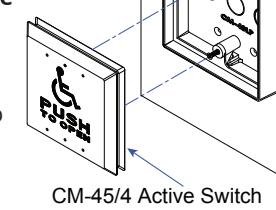
2. Screw in the supplied #6-32 screws only a few threads deep into the back box and fit in the assembled CM-45/4 by locating the holes on the back plate and
Mount Enclosure
Surface Wall
sliding it down in place on the back box.
3. Fit the HEX key through the hole on the faceplate and completely tighten the #6-32 screws in place.
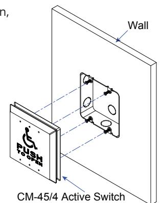
Flush Mount Installation
- 1. With the back box already roughed-in, screw in the supplied 6-32 screws only a few threads deep into the back box and fit in the assembled CM-45/4 by locating the holes on the back plate and sliding it down in place on the back box.
- 2. Fit the HEX key through the hole on the faceplate and completely tighten the #6-32 screws in place.
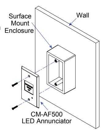
CM-AF500 MOUNT INSTALLATION
Surface Mount Installation
1. Position the back box (CM-34BL) on the wall in the desired location and use the supplied #10 x 1 pan head screws with the green PVC anchors to mount the back box to the wall.
Note: the back box will need the screw holes drilled out prior to mounting it to the wall.
2. Position the CM-AF500 so that the holes on the faceplate line-up with the screw holes on the back box and tighten the supplied #6-32 screws securely in place.
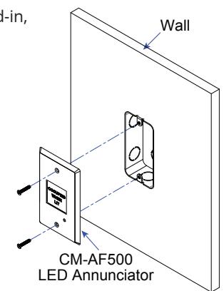
Flush Mount Installation
1. With the back box already roughed-in, position the CM-AF500 so that the holes on the faceplate line-up with the screw holes on the back box and tighten the supplied #6-32 screws securely in place and completely tighten the #6-32 screws in place.
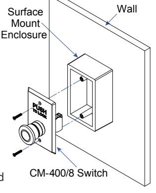
CM-400/8 MOUNT INSTALLATION
Surface Mount Installation
1. Position the back box (CM-34BL) on the wall in the desired location and use the supplied #10 x 1 pan head screws with the green PVC anchors to mount the back box to the wall.
Note: the back box will need the screw holes drilled out prior to mounting it to the wall.
2. Position the CM-400/8 so that the holes on the faceplate line-up with the screw holes on the back box and tighten the supplied #6-32 screws securely in place.
Wall
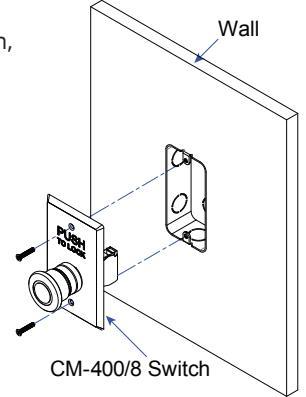
Flush Mount Installation
1. With the back box already roughed-in, position the CM-400/8 so that the holes on the faceplate line-up with the screw holes on the back box and tighten the supplied #6-32 screws securely in place.
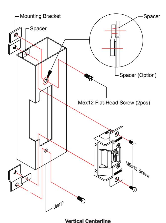
CX-ED2079 'UNIVERSAL' ELECTRIC STRIKE INSTALLATION
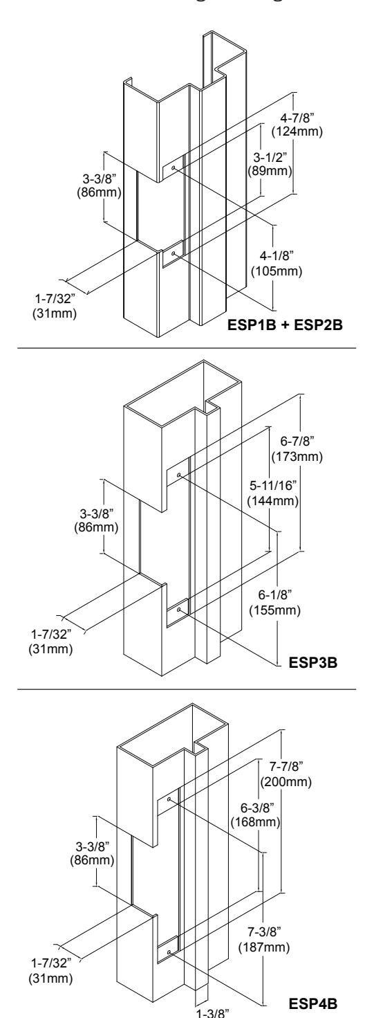
- 1. Prepare the door jamb as per the appropriate drawing.
- 2. Install mounting brackets to jamb using M5x12 screws and pressed metal nuts. Do not tighten.
- 3. Spacers are used to assure flush final assembly of faceplate into jamb. Add one of more spacers between jamb and mounting bracket when face plate extends beyond the jamb. When the faceplate sits inside the jamb, spacers must be added between the mounting bracket & the lip bracket. Make sure clearance hole in spacer aligns with hole in mounting bracket.
Note: The products are intended to be installed in accordance with the installation wiring diagram, mechanical assembly drawings provided with each product, the local authority having jurisdiction (AHJ) and the National Electric Code, NFPA 70. When installed in fail secure mode, the local authority shall be consulted with regard to the use of possible panic hardware to allow emergency exit from the secure area.
The electric door strike shall be installed in such a way and in such a location so as to not impair the operation of an emergency exit device or panic hardware mounted on the door.
- 4. Connect wires coming from the low voltage side of the transformer to wires (black) from strike.
- 5. Install electric strike jamb by attaching with # 10-32 screws and lockwashers.
- 6. Secure M5x12 screws holding mounting brackets to jamb.
(36mm)
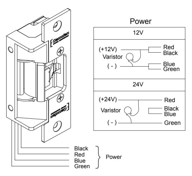
CONNECTIONS OPERATIONS
POWER 12VDC
Red/Black: +12V Blue/Green: Ground
24VDC
Red: +24V
Black/Blue: -
Green: Ground
A varistor is provided to protect/prevent strike from spikes. Connect varistor between input wires.
Note: For UL 294 / UL 1034 compliance the door strikes are to be powered via a UL 294/ UL 603 class 2 power limited output from a control panel and or power supply. Furthermore, when powered by AC/DC the units shall use a UL regulated UL 294/UL 603 power limited class 2 output rated 12/24V with AC on indicator.
How to modify fail-safe to fail-secure or vice versa.
- 1. Loosen the screw as per the product diagram below.
- 2. Rotate the set plate 180°and slide the plate until it is properly seated.
- 3. Tighten the screw.
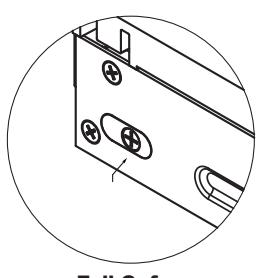
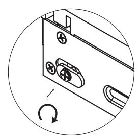
Fail Safe Changing
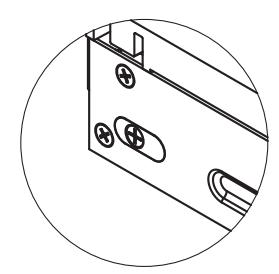
Fail Secure
ORDERING INFORMATION FOR REPLACEMENT PARTS
| Item | Part Number | Description |
|---|---|---|
| 1 | 60-31A037 | Red/Green Aura PC Board |
| 2 | 60-42C012 | Square Aura Insert |
| 3 | 60-40E033 | Advanced Logic Control Relay and 2 Amp Power Supply in pre-wired metal cabinet |
| 4 | CX-MDA | Magnetic Door Contact |
| 5 | 60-42C019 |
Mounting Box, Flush Aura Enclosure. Flame/Impact Resistant Black Polymer (ABS)
6-1/2"W X 6-1/2"H X 2"D |
| 6 | 60-42C010 |
Mounting Box, Surface Aura Enclosure. Flame/Impact Resistant Black Polymer (ABS)
5-1/4"W X 5-1/4"H X 2"D |
| 7 | 60-81C021 |
English Self-Adhesive Vinyl Sign
''WAIT FOR DOOR TO CLOSE'' |
WC11PS SERIES RESTROOM CONTROL
INSTALLATION INSTRUCTIONS
| Notes : | |
|---|---|
| 1. | |
| 2. | |
| 3. | |
| 4. | |
| 5. | |
| 6. | |
| 7. | |
| 8. | |
| 9. | |
| 10. | |
| 11. | |
| 12. | |
| 13. | |
| 14. | |
| 15. | |
| 16. | |
| 17. | |
| 18. | |
| 19. | |
| 20. | |
| 21. | |
| 22. | |
| 23. | |
| 24. | |
| 25. | |
| 26. |
Questions? Call us toll-free at 1-877-226-3369 or technical support 905-366-3377 (ext. 505)
Call: 1.877.226.3369 / 905.366.3377 Visit: www.camdencontrols.com


RESTROOM SIGNAGE
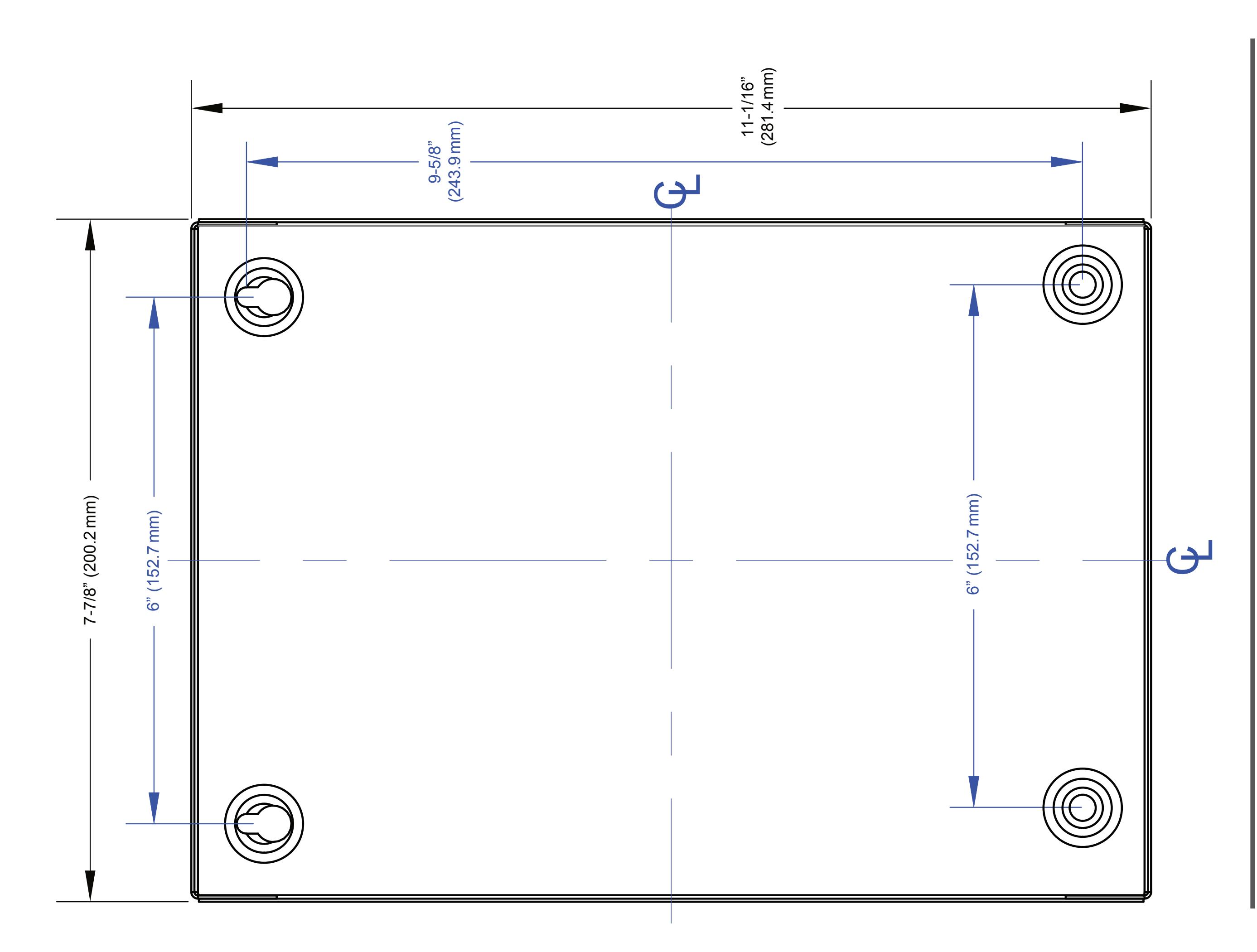
CABINET BASE & MOUNTING TEMPLATE