CX-SA-1 Manual
Open the original PDF document
View PDFSA-1 FEATURES:
- CAN BE POWERED FROM 12 TO 24 VOLTS AC OR DC
- SEPARATE MOMENTARY AND EXTENDED TRIGGER INPUTS INCREASE APPLICATIONS
- CONTROLLED RELEASE OF LOCK RELAY WHILE MAINTAINING OPERATOR RELAY FOR SPECIAL DOOR HOLD OPEN APPLICATIONS.
- DRY CONTACT AND HOT TRIGGER INPUTS
- HOT TRIGGER INPUTS CAN BE AC OR DC
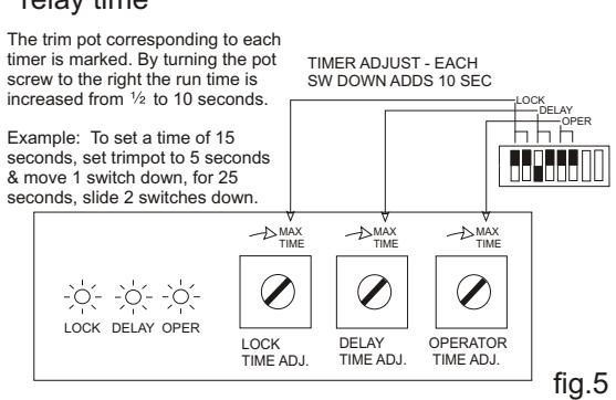
- LOCK RELAY, OPERATOR RELAY, AND DELAY TIMERS CAN BE INDIVIDUALLY ADJUSTED FROM 1/2 TO 30 SECONDS.
- ALL TIMERS USE FIXED TIME RANGE TRIM POTS AND TIME BLOCK ADD'N SWITCHES TO KEEP TIME SETTING EASY
- SEPARATE LEDS SHOW DELAY TIMER, AND LOCK AND OPERATOR RELAY STATUS FOR TRUE INDICATION AT ALL TIMES.
- WILL RETRIGGER BEFORE THE SEQUENCE IS FINISHED
- FULL 36 MONTH WARRANTY FROM DATE OF PURCHASE
Specifications
OPERATING VOLTAGE.....12 through 24 Volts, AC or DC STAND BY CURRENT........... DC 12 VOLTS - 8 mA AC 24 VOLTS - 18 mA OPERATING CURRENT........ DC 12 VOLTS - 48 mA AC 24 VOLTS - 63 mA TRIGGER INPUT ............. LESS THAN .5 mA 6-48 VDC, 12 - 48 VAC RELAY CONTACTS................ 2 A @ 24V, FORM 'C' SIZE 105mm (4.1") WIDE, 85 mm (3.4") HIGH 15 mm (0.7") DEEP
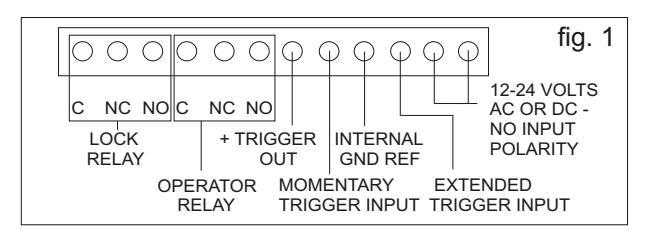
The terminal strip provides access to the lock & operator relay contacts, trigger inputs, and power connections.
A SMALL TIP TO HELP PROTECT YOUR SA-1 DOOR SEQUENCER
Locks such as maglocks and door strikes are essentially large electro-magnets. When power is removed from such locks, a high voltage is generated by the collapsing magnetic field. This voltage (called Back EMF or Kickback) will eventually damage the relay contacts.
Fortunately, it is possible to virtually eliminate these effects by simply connecting the proper suppression device across the relay contacts. This device is called a MOV (Metal Oxide Varistor). Use the supplied 35 volt MOV with either AC or DC power to the electric lock.
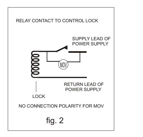
USE THIS COMPLIMENTARY MOV TO EXTEND THE LIFE OF YOUR SA-1
MOV
Model #
SA-1 (MK5) CX-
The SA-1 Door Sequencer is a highly versatile circuit designed to allow easy interface solutions to a wide variety of door installation situations. A single input can unlock and open a door, re engage the lock, hold the door open for an indefinite period of time, and automatically close and re-secure the door at the end of the trigger.
The SA-1 MK5 is a digital version of the MK4. Because it is digital, we've been able to improve its performance and add some requested features. Timer setting is more accurate and you can now use AC voltage for a hot trigger input reducing the need for extra interface relays. The latest versions of this product have improved noise immunity.
Latching Relay Option
A flick of a switch changes the SA-1 into a Latching Relay . The 1st push of a button starts the Sequencer cycle - the same as the other modes. However, one or both relays will remain on after the timers have expired until the button gets pressed again.
With the latching relay operation triggered off the momentary input, the extended trigger remains operational. The activation of the extended trigger overrides the latching relay so the relays won't be latched on after the extended trigger ends.

5502 Timberlea Dr Mississauga ON L4W 2T7
Toll-Free: (877) 226-3369 Fax No.: (905) 366-3378
or, email us... techsupport@doorcontrol.com
Printed in Canada

2006 Camden Door Controls Inc.
Momentary mode triggering
The momentary mode is designed to accept either dry contact (N.O.) or hot (applied voltage) triggers of arbitrary length. Once the preset period for each of the timers has expired, that function will release regardless of whether or not the trigger input has been removed. The momentary (MOM TRIG) is selected by taking the +OUT output to the MOM TRIG input via dry contacts, or placing 12-24 VDC between the MOM TRIG input and ground (GND REF) terminals.
Latched mode triggering
This switch in the "down" position changes the momentary trigger into the latching mode trigger. In this mode, the operator relay will stay on indefinitely. The Lock relay may also be maintained depending upon the position of the control switch. (See Fig. 4) The next trigger will release both relays immediately even if the timers haven't expired. Activation of the extended trigger will override the latching mode. This prevents the relays from remaining latched on after the extended trigger ends.
Extended mode triggering
The extended mode is designed to accept either dry contact (N.O.) or hot (applied voltage) triggers of arbitrary length. The operator relay will be maintained for the duration of trigger input. The lock relay may also be maintained depending upon the position of the control switch (see fig.4). This allows the door to be held open at length without damaging intermittent duty strikes. If the trigger is removed prior to any (or all) timer(s)expiring, the SA-1 will default to momentary mode.
Lock relay release during hold open function
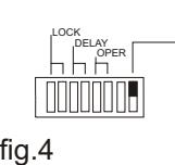
When using the extended trigger mode or the latching relay mode, the lock relay can match the operator relay output or be released when the lock timer times out.
To maintain the operator relay and keep the lock insecure, move the switch to the up position as shown. If the switch is in the lower position after the lock timer times out, the lock relay will release regardless of the state of the extended trigger input or the mode selected.
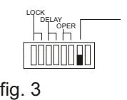
Adjusting delay timer, and lock and operator relay time
Mixed mode triggering
The SA-1 has been designed to give you the greatest flexibility in your installations. There are only a few things to remember in selecting your trigger inputs. The extended trigger ON blocks both the momentary and latching modes. Therefore this is the trigger to use for door hold open applications. However, the momentary trigger left active will not prevent the operation of the extended trigger. This makes it the ideal input for those situations where the button is prone to sticking.
Extended mode example
Long term door hold open (lock re-secures after door opens)
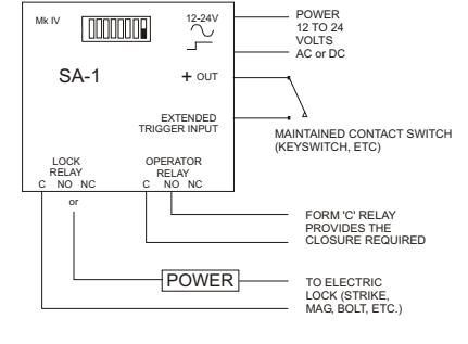
NOTE: USE THIS HOOKUP FOR INTERMITTENT DUTY STRIKES
fig.6
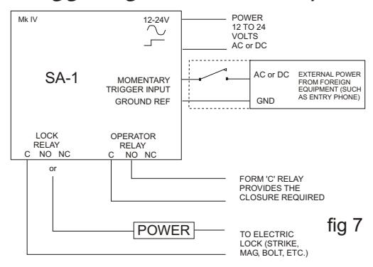
Triggering from a hot output
Triggering from hot output and dry contacts in combination
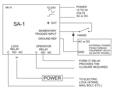
NOTE: The diode connecting the foreign equipment is to protect the foreign equipment and is not required by the SA-1 fig .8
Vestibule control examples
Operating 2 door vestibule, no electric lock
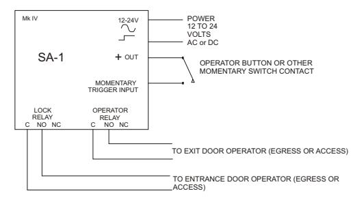
fig.9 NOTE: ONE SA-1 IS REQUIRED FOR ACCESS DIRECTION AND ONE FOR EGRESS DIRECTION.