CX-PS300UL Manual
Open the original PDF document
View PDF

Electrified Locks, Relays and Timers
CX-PS300UL POWER SUPPLY / CHARGER
INSTALLATION INSTRUCTIONS
1. DESCRIPTION
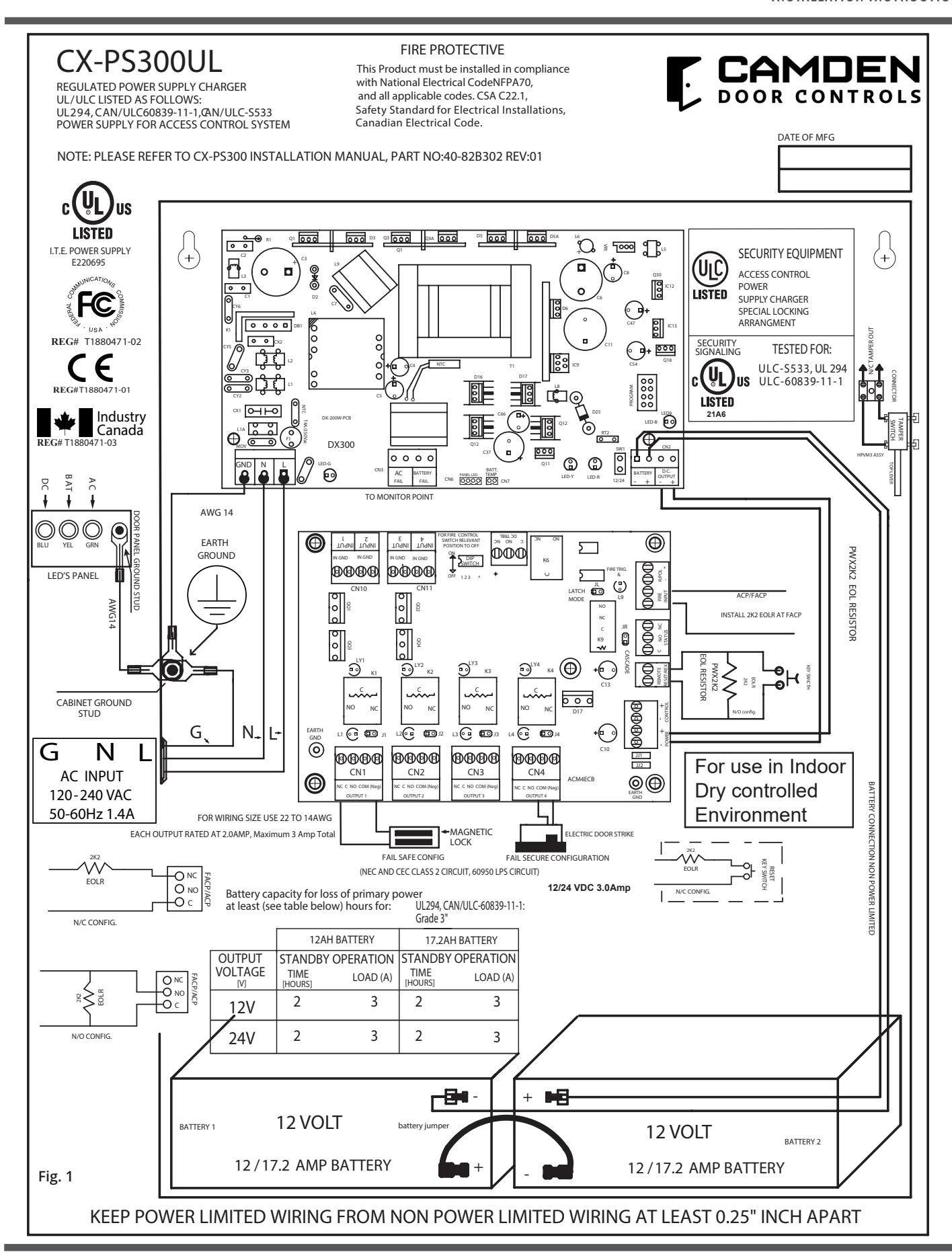
The CX-PS300UL series of power supply/charger supplies a total of 3-amp nominal continuous supply current @ 12/24V DC outputs. It is installed in a large sheet steel enclosure capable of accommodating one or two 12 Ah lead acid rechargeable batteries. The camden CX-PS300UL has been evaluated for ULC-S533, UL294 and ULC-60839-11-1. This power supply is not intended to power fire notification appliances (Horns, Strobes & Bells).
2. GENERAL SPECIFICATIONS
- 1. Input = 120 240V AC 50-60Hz, 1.4 Amp maximum.
- 2. Output 3 Amps continuous supply current PF 0.6 a t nominal 12/24 V DC.
- 3. Built-in dedicated charger for sealed lead acid or gel cell type batteries.
- 4. Maximum battery charging current 1.5Amps (not part of the max output current rating).
- 5. Automatic switch over to stand-by battery upon AC failure or below V .
- 6. Battery presence detection within 10 seconds.
- 7. Temperature Compensated Battery Charger. (EN54-4 only,not UL evaluated)
- 8. Battery Charger Monitor.
- 9. Battery load test every 48hr.
- 10. Battery test result indication.
- 11. Battery Reversal protection.
- 12. Low Battery indication at 11.40/22.80 Volts.
- 13. Low Battery disconnect at 10/20.2 Volts.
- 14. Low Battery, Battery disconnect, No Battery presence, battery charger trouble reporting. (See FAULT TABLE)
- 15. AC input indication by Green LED. (LED on when AC is present).
- 16. AC Fault CMOS Relay contact for AC failure
- 17. LEDs display on enclosure door (Green, Yellow, Blue).
- 18. DC output indication by Blue LED, on board and enclosure.
- 19. Overload and short circuit protection on DC output.
- 20. Battery charging leads included.
- 21. Board Dimension: 195mm x 110mm
- 22. Enclosure Dimension: 338 x 448 x 110mm (HP346 for 12Ah Battery)
3. TECHNICAL SPECIFICATION:
| Output Voltage | 12/24 V DC Regulated. ClassE, unsupervised |
|---|---|
| Output Amperage | 3 Amp |
| Ripple | 50mVp-pmax |
| Charging Current | 1.5A Max, and not part of max output rating |
| Battery Charging Voltage | 13.8V/27.6V Nominal |
| Operating Temperature | 0 ˚C to 49 ˚C |
4. PERFORMANCE RATINGS
UL294 Performance Levels:
| Model | Product Type | Line Security |
Destructive
Attack |
Endurance | Standby Power |
|---|---|---|---|---|---|
| CX-PS300UL | Power Supply | I | I | IV |
III (when used with 12Ah
battery) |
CAN/ULC-60839-11-1 Performance Grades:
| Model | Product Type | Grade | Grade Achievement | |
|---|---|---|---|---|
| CX-PS300UL | Power Supply |
3 (when used with 12 Ah
battery) |
Connect AC & battery
trouble relay outputs to a grade 3 control unit, to achieve Grade 3. |
|
5 . LED INDICATIONS
1. Green LED- AC indicator
- a. On when AC present.
- b. The AC fail Relay activates (opens) within 60 seconds after AC failure.
2. BlueLED– DC Power indicator
a. Powered directly from the power supply DC output and indicates output is present.
3. YellowLED– Battery Charging and Fault indicator
a. The Yellow LED flashing indicates the battery is charging and is also used to indicate various Fault conditions. See the Fault Condition and Indication table for details.
4. RedLED– Battery/ Charger test Indiicator for Pass or Failure.
a. The Red LED indicates a Battery test Failure or a Battery charger failure in conjunction with the Yellow LED to indicate other Fault Conditions. See the Fault Conditions and Indication table for details.
6. RELAY / OUTPUTS:
| Output | Output Type | Description |
|---|---|---|
| AC FAIL |
NORMALLY CLOSED
OPEN = FAULT |
TRIPS WITHIN 60 SEC. AFTER AC FAILS CMOS
RELAY RATING: 30V DC, 60 mA, 16 Ω |
| BATTERY FAIL |
NORMALLY CLOSED
OPEN = FAULT |
BATTERY PROBLEM
CMOS RELAY RATING: 30V DC, 60mA ,16 Ω |
7. FAULT CONDITION & INDICATIONS:
| FAULT | LED-G | LED-Y | LED-R |
BATT
RELAY |
AC RELAY | LED-B |
|---|---|---|---|---|---|---|
|
BATTERY
REVERSED OR NOT CONNECTED |
ON | OPEN | ||||
| BATTERY LOW | ON | OPEN | ||||
|
BATTERY
DISCONNECTED |
ON | OPEN | ||||
|
BATTERY
TEST FAIL |
ON |
5 RAPID FLASHES
STOP 1 SECOND REPEAT UNTIL BATTERY IS REPLACED |
OPEN | |||
| BATTERY TEST OK | OFF |
3 FLASHES
1 SEC ON/OFF |
||||
| CHARGER FAIL |
10 RAPID
FLASHES 2 SECONDS STOP AND REPEAT UNTIL OK |
OPEN | ||||
| AC FAIL | OFF |
OPEN
WITHIN 60 SEC |
||||
|
DC FAIL /
OVERLOAD |
OFF |
8. BATTERY OPERATING VALUES
| Parameter | Output | Description |
|---|---|---|
| Battery Disconnect voltage | 10/20.2V |
When AC is off, the battery is disconnected when the battery
voltage drops below this value. The battery is only reconnected when the AC is restored. |
|
Minimum battery voltage to
pass battery test |
11.50V
23.0V |
Red LED should flash for 1 sec ON/OFF during 2 minutes
testing. 5 rapid flashes and 1 second pause indicates battery failure. In such case replace battery. |
|
Low Battery Voltage
Warning |
11.40V
22.80V |
If the out put voltage drops below this value, a voltage low
warning is generated. See Fault Conditions and Indication table. |
9. INSTALLATION INSTRUCTIONS
This power supply should be installed in compliance with National Electrical Code, NFPA70 as well NFPA72 National Fire Alarm Code, CSA C22.1, Safety Standard for Electrical Installations, Canadian Electrical Code, Part I, CAN/ULC-S524, and all applicable Local Codes. Installation to be performed by suitably qualified personnel. The power supply shall not be installed in the fail secure mode unless permitted by the local authority having jurisdiction, and shall not interfere with the operation of Listed panic hardware.
NOTE: Connect the Mains AC input 120/240V AC as shows in the installation diagram. Entry knocks out on the left of the enclosure. Keep low voltage wiring away from the AC wiring.
- 1. Mount the power supply in the desired location using the 4 mounting holes. NOTE: For use in indoor protected area with controlled environment only. Do not install power supply on exterior doors.
- 2. With the main power disconnected, connect the LEDs to the AC input terminal block, respecting the wiring phase and polarity : Ground/Earth=Green/Yellow, Neutral = Blue (White), Live =Black (Brown). This equipment must be connected to the 120-240 Volt Mains via a readily dedicated accessible external disconnect device with maximum 15 Amp branch protection. Select the operating output DC voltage 12/24 with the jumper SW1. SW1 ON = 12V DC, SW1 OFF = 24V DC.
- 3. Do not connect the battery at this time.
- 4. Switch ON the AC power supply and with that Green LED will turn ON indicating AC is present and the AC Fault Relay will be energized "ON" (closed). When the AC is off, the AC Fault Relay will drop open within 60 seconds (Factory set) activating the CMOS output "AC Fail". Connect this output to relevant monitoring devices.
- 5. Verify the DC output voltage. It should be13.20V DC or 26.40V DC (max). Blue DC LED will turn ON indicating DC output is OK.
- 6. Yellow LED will only turn on along with open BAT FAULT CMOS relay to indicate the Battery is not attached or connected with reversed polarity.
- 7. Connect the Battery or Batteries with respective polarity. Note: Battery should not be connected if the AC is not present first.
- 8. If the battery is connected with the correct polarities, the Yellow LED will turn OFF (See Fault Conditions and Indications Table). Within one minute the Battery Fault Relay will restore and the Yellow LED will flash once every 2 seconds.
- 9. If the battery is connected with reverse polarity, the Yellow LED will remain ON. (See the Table Fault). The CMOS relay will be open indicating Battery Fault. Connect this output to relevant monitoring devices.
- 10. Connect the devices to be powered to the output terminals marked "Vo- Vo+".
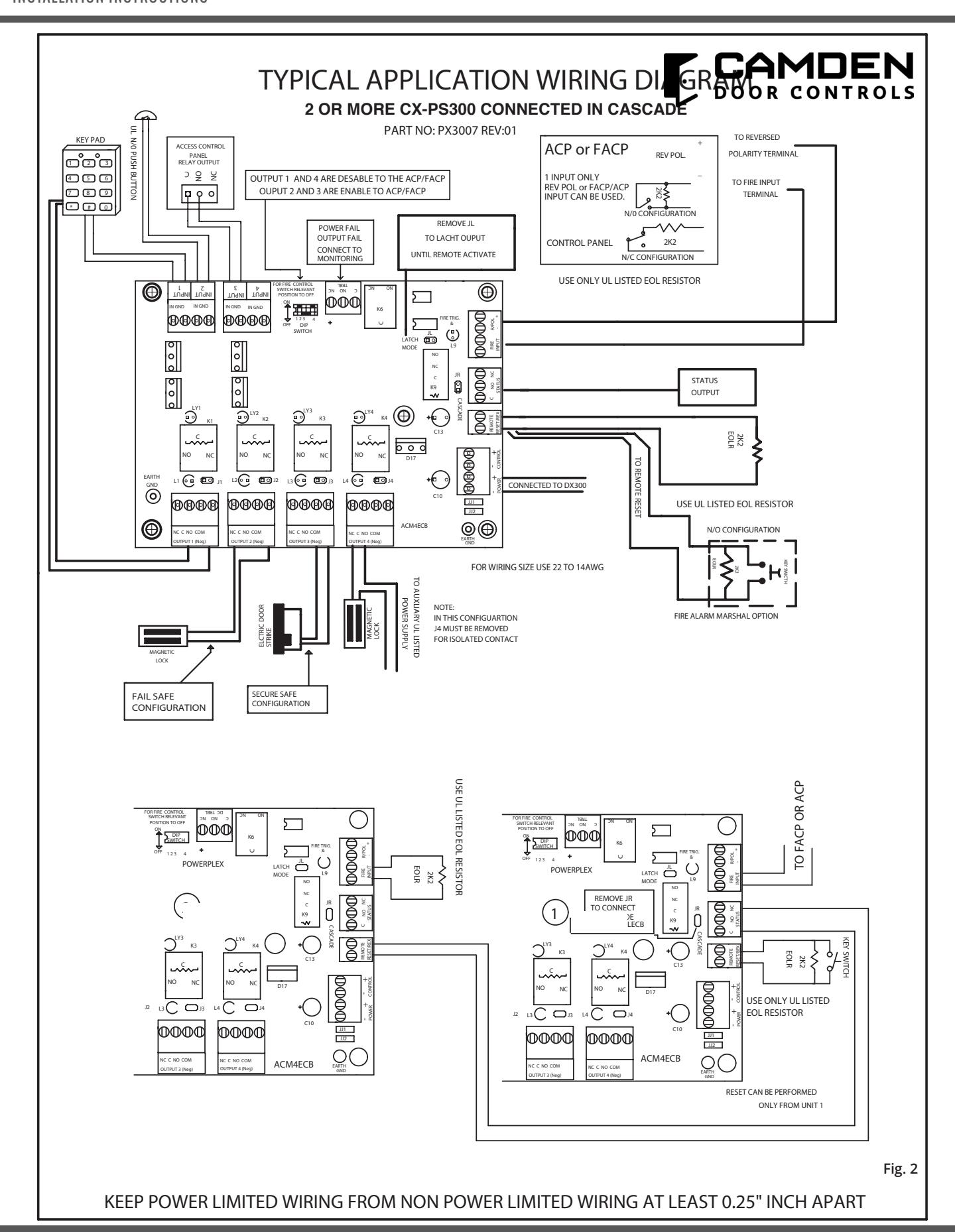
- 11. See below Fig 1 & Fig 2. for installation of PD4ECB, PD8ECB, MOM8ECB and ACM4ECB need 2 EOLR Resistors (2K2) provided.
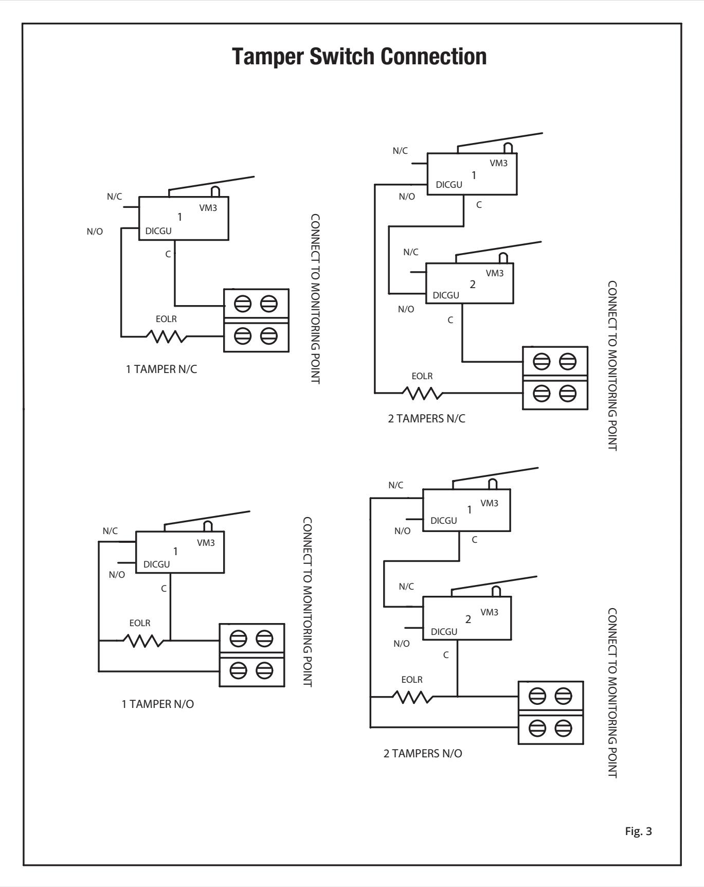
- 12. If Tamper Switch is required, use part # TSW1-02 or TWS2-02 (Refer Fig 3).
- 13. Use 2K2 EOLR (End Of Line Resistor) Part #EORL-PWX2K2.
- 14. Connect the fault relays to FACP or ACP for trouble indication.
- 15. Secure the enclosure with the screw or with the Key Lock (if provided).
10. ACM4ECB
DESCRIPTION:
The ACM4ECB is a distribution controller to be used with card Access Control, Egress Doors. It provides 12/24V DC through 4 outputs rated 2.0A (max. 3A total) each with electronic over-current protection set at 2.5A. The 4 outputs will switch ON or OFF security devices such as Magnetic Locks, Door Strikes, etc. It is connected to FACP or ACP via NO or NC configurable contact input using 2K2 EOLR (Part #EORL-PWX2K2). It also has an input for Reversed Polarity triggering. The ACM4ECB has 2 Dry Contact "Form C" relay outputs, one is to indicate output status, and another to indicate DC failure on any of the 4 outputs, due to overcurrent or short.
Installation:
1. Output Connections
There are 4 selectable outputs suitable for FAIL safe config and FAIL secure config.
- a) For FAIL safe operation, connect the positive (+) lead of the device to normally closed (NC) and the negative lead to COM "Neg", connector CN1 to CN4. DC power is present in normal condition and switched OFF when the fire alarm from FACP or ACP or Reverse Polarity input is triggered. FAIL Safe operation devices such as, Magnetic Lock should be connected to this output as show in Fig. 2.
- b) For FAIL secure operation, connect the positive(+) lead to Normally Open (NO) instead of normally closed (NC). DC power is not present in normal condition and will switch ON when the FACP or ACP or Reverse Polarity input is triggered. FAIL secure operation devices such as Door Strikes should be connected to this output.
2. Fire Alarm and Access Control Interface
Normally Open (NO), Normally Closed (NC) input or Polarity Reverse (Rev. Volt.) input are available to trigger the ACM4ECB operation. Connect the positive(+) and Negative(-) from the FACP or ACP to the REV. VOLT terminals observing the polarity, (polarity is referenced in alarm condition) or connect the NO or NC from the FACP or ACP output to the "Fire Trigger" terminals. Install PWX2K2 2k2 (EOLR) resistor at the FACP or ACP as show in Fig. 1. Note: No ELOR on Rev. Pol.
3.Engineering RESET/REX Input
This option is avaliable when the Jumper JL is removed (JL OFF). This will cause the ACM4ECB to latch upon receiving Input from the FACP or ACP with this option in place and when the FIRE/ACP TRIGGER resets.
JL ON will cause the unit to follow the FIRE/ACP TIGGER. Install PWX2K2 2.2K (EOLR) resistor at the Key Switch or Push Button to perform this operation.
4. Relay Output
- a) DC Fail: When one or more of the 8 outputs fail due to over current or short circuit condition, the DC fail Relay will open. Connect this output to monitoring device. (28V DC, 300mA)
- b) Status Output: When the FACP or ACP input activates this will cause the dry contact Relay Form "C" to change state (de-energize). Connect this output to monitoring device. (28V DC, 300mA)
5. ACM4ECB LED INDICATION
L1 to L4 are the Output RED LEDs, when ON they indicate DC is present (enable), and the Output relays are energized.
When OFF, they represent Relay is de-energized and the output is OFF, NO DC present (disable). LD1 to LD4 are Yellow LEDs. They indicates overload or short on the output. The output current limit is set @ 2.5Amp, rated at max 2.0Amp. L9 Green LED is normally OFF. It will switch on upon receiving an alarm from the FACP/ACP. This LED will stay ON following the status of the FACP/ACP input. If JL was removed, this LED will stay ON until the manual RESET circuit resets.
6. Access Control Panel (ACP)Trigger input.
There are 4 inputs split between CN10 and CN11, each with four terminals, two IN and two GND. Activation of the inputs is achieved by shorting IN and GND terminals of the respective inputs.
7. FACP/ACP Input Programming
Selectable Output to be Irrelevant on Fire Activation to have the output relay activation follow the FACP or ACP input place the DIP switch corresponding to desired relay to the "OFF" position. In the "ON position, the correspondent output relay will not be affected by the FACP,ACP or Rev. Pol input.
CX-PS300UL POWER SUPPLY / CHARGER
INSTALLATION INSTRUCTIONS
8. Isolated Output Configuration
If any of the outputs requires to be solated DRY CONTACT, remove the respective Jumper J1 through J4 to achieve this configuration, Form "C", (C NO NC) available to connectors CN1 through CN4. This connection is now isolated from the internal power source. Relay Rating: 28V DC, 2A. PF 0.6