CX-ED1959-MB Manual
Open the original PDF document
View PDF

Electrified Locks, Relays and Timers
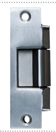
CX-ED1959 Outdoor Gate
Electric Strike
INSTALLATION INSTRUCTIONS
THIS PACKAGE INCLUDES:
1- 4 PIN power connector (12V) 1- Varistor
1- 4 PIN power connector (24V) 2- #10 - 1 x 1/4" self-tapping screws 4- Wire nuts 4- #12 - 24 x 1/2" machine screws
2- Mounting brackets 1 - Mounting Box

1. GENERAL DESCRIPTION
Camden CX-ED1959-MB Grade 1 Outdoor Gate Strike for cylindrical and mortise locksets (without dead bolts) offers best-in-class strike quality, performance and durability. The universal design delivers unparalleled application flexibility, with field selectable voltage and fail safe/fail secure operation for use in wood or metal jambs.
2. SPECIFICATIONS
| Voltage | 12/24V DC | |
|---|---|---|
| Current Draw | 280mA / 140mA | |
| Static Strength | 1500 lbs | |
| Dynamic Strength | 70 ft-lbs | |
| Endurance |
1,000,000 Cycles (Factory Tested)
250,000 cycles (UL Verified) |
|
| Latch Open/Ins | 1-9/16" x 7/8" (40mm x 22mm) | |
| Mode |
Field Selectable
Fail Safe/Secure |
|
| Duty | Continuous | |
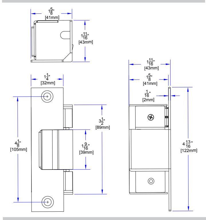
| Dimensions (Body) |
4-13/16"H x 1-5/8"W x 1-11/16"D
(122 mm x 41mm x 43mm) |
|
UL294 PERFORMANCE LEVEL
| Line Security | Level I |
|---|---|
| Attack Level | Level I |
| Endurance Level | Level IV |
| Standby Power | Level I |
3. DIMENSIONS
NOTE
- The products are intended to be installed in accordance with the\ninstallation wiring diagram, mechanical assembly drawings provided with each product, the local authority having jurisdiction (AHJ) and the electric code, NFPA 70. When installed in fail secure mode, the local authority shall be consulted with the regards to the use of possible panic hardware to allow emergency exit from the secure area.
- The electric door strike shall be installed in such a way and in such a location so as to not impair the operation of an emergency exit device or panic hardware mounted on the door.
4. INSTALLATION
Note: Choose the appropriate option based on the type of frame or gate you have. For a wooden jamb, drill holes to install the strike and use supplied " self-tapping screws for mounting.
Option 1 For Hollow Metal Frame
- Determine the location where the electric strike will be installed on the door frame. This should align with the location of the latch on the door.
- Mark the outline of the electric strike on the jamb using a pencil or marker
- 3. Using a chisel, router, or jamb saw, cut out the mortise in the jamb along the marked outline. The size of the mortise should match the size of the electric strike. Make sure to cut to the depth specified in figure 4.1.
- 4. Drill holes to mount the provided mounting bracket using 1/4" drill hits
- 5. Use provided #12 24 x 1/2" machine screws to mount the brackets included in the package.
- Test fit the electric strike in the mortise. Make any necessary adjustments to ensure a proper fit.
- 7. Mount the strike onto the bracket using the included " machine screws.
Option 2 For ANSI Frame
- 8. Make sure that the door jamb/gate has an appropriate cutout to accommodate strike assembly, If not then, refer to the dimension section and cut the jamb if required.
- 9. Use the supplied #12 24 x 1/2" machine screws to secure it.
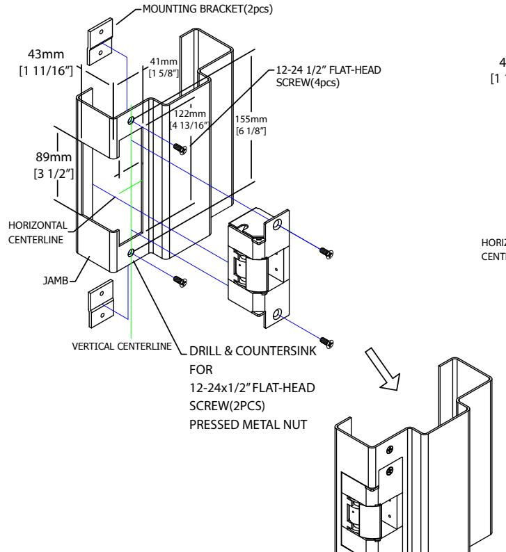
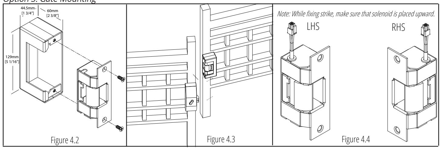
Option 3 Gate Mounting
- 10. Secure the supplied mounting box onto the gate through welding or with the help of screws (see figure 4.3).
- 11. Secure the strike inside the box with the help of supplied " machine screws (see figure 4.2).
- 12. Run the wires from the electric strike through the jamb and into the door. Connect the wires to the appropriate terminals on the electric strike as mentioned in section 5.
Option 1: Hollow Metal
Option 2: ANSI
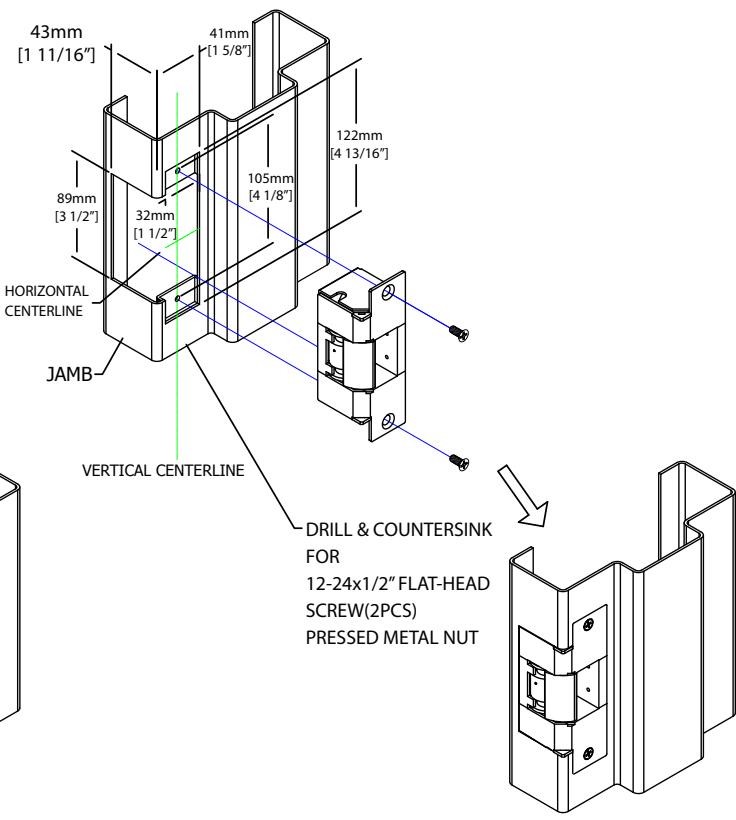
Figure 4.1
Option 3: Gate Mounting
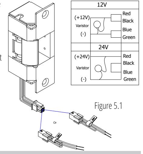
5. CONNECTIONS
1. Firstly, verify that voltage required to operate Electric strike is compatible with supply voltage of the installation. POWER: Red/Black, Blue/Green (12 VDC)
Red, Black/Blue, Green (24 VDC) Red/Green (Short Black, Blue)
- 2. Splice strike wire with the supplied wire and make sure to attach provided varistor as described.
- 3. A Varistor is provided to protect strikes from voltage spikes. Connect the varistor between two input wires. The connection of varistor varies based on input voltage. Please see below for more details;
| Dower | Varistor Connection | ||
|---|---|---|---|
| Power | +ve end | -ve end | |
| 12V | Red/Black | Blue/Green | |
| 24V | Red | Green | |
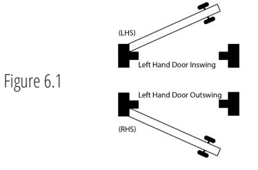
6. OPERATION
Left Hand/Right Hand Door Assembly
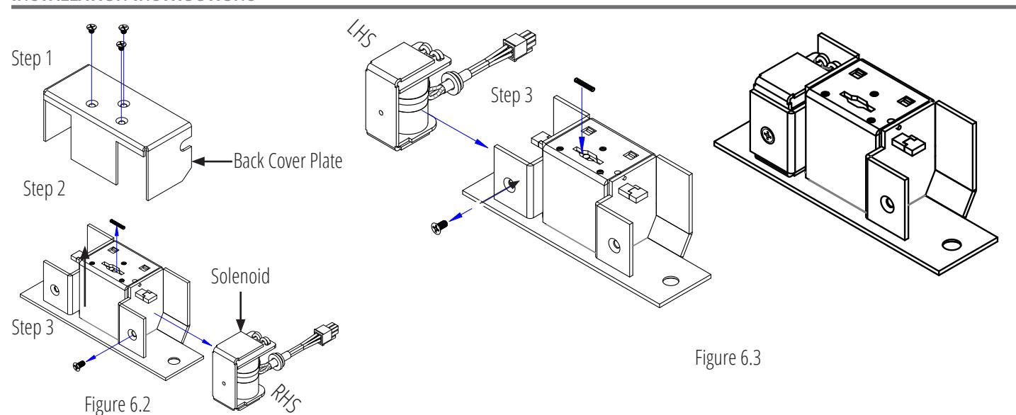
The strike is symmetrical in design and thus, it can be installed on either left-handed or right handed doors (Inswing or Outswing) (figure 6.1). The strike comes with a solenoid and its direction can be changed based on the requirements. Follow these steps to change the direction of the solenoid:
- 1. Loosen and remove the screws from back the of the strike as shown in figure 6.2.
- 2. Remove back cover plate from the assembly.
- 3. Loosen and remove solenoid screw and change solenoid direction as per requirements. (See figure 6.3 for more details).
- 4. Finally follow the same process in reverse chronological order for reassembling.
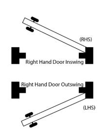
To determine the location/side of the solenoid, see following table and figure 6.1.
| Door Side | Swing Type | Solenoid Location (If wires are facing upward) | ||
|---|---|---|---|---|
| Left Hand Door | Inswing | Left Hand Side (LHS) | ||
| Outswing | Right Hand Side (RHS) | |||
| Right Hand Door | Inswing | Right Hand Side (RHS) | ||
| Outswing | Left Hand Side (LHS) | |||
INSTALLATION INSTRUCTIONS
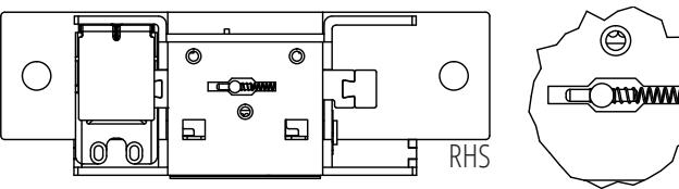
Fail Safe/Fail Secure Mode
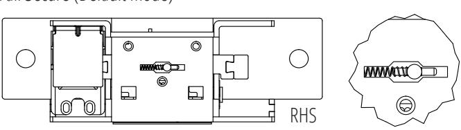
The strike comes with fail-secure mode by default. However, it can be changed by reversing the spring direction. To change the direction of the spring, kindly refer following steps:
- 1. Loosen and remove the screws from the back of the strike as shown in the Figure 6.4.
- Remove the back cover plate from the assembly.
- Remove the tiny spring, shift the slider to the other side, and reinsert the spring. (By-default the spring must be located to the Left Hand Side (Fail secure mode) (Considering keeper faces upward))
- For reassembling, repeat the process in reverse chronological order.
Note: The spring is very delicate and needs to be handled with care. Fail Safe

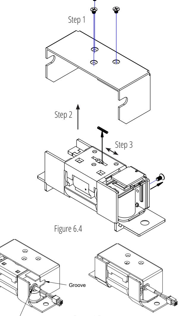
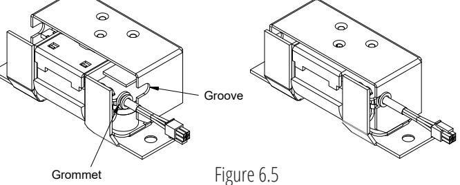
Important Note: After making any changes mentioned above, make sure that the rubber Grommet sits accurately into the groove of the back cover plate as shown in figure 6.5 while reassembling.


Rev.: March 21, 2023 Part No.: 40-82B235