CX-DE1200 Maintenance Manual
Open the original PDF document
View PDFElectrified Locks, Relays and Timers
Delayed Egress Lock Maintenance Manual
INSTRUCTIONS
These systems are meant to delay the egress in certain but not all cases. The delayed egress device should be automatically unlocked in case of a fire, earthquake etc. The door should be unlocked at once when the sprinkler or fire detection system goes off or during a power outage. In other words, it's a matter of public safety if an emergency evacuation is required.
FOR SPECIAL LOCKING ARRANGEMENT: The delayed egress lock must be wired to a fire alarm system per NFPA code or other regulations to bypass the time delay in the event of a fire. Contact your local code authority to verify compliance with fire and building codes.
RECOMMENDATIONS FOR INSPECTION AND MAINTENANCE:
- 1. It is the responsibility of the installer to ensure that the Dip Switch 8-1 setting complies with local Fire, Building and Life Safety Codes. All installations must be approved by the local Authority Having Jurisdiction (AHJ).
- 2. This product and all related accessories or parts must be inspected and maintained on a quarterly basis.
- 3. Contacting surfaces of the electromagnetic lock and armature plate must be kept free of contaminating materials. Surfaces must be cleaned periodically with a non-abrasive cleaner.
- 4. All mounting fasteners must be inspected on a quarterly basis. When properly installed, the ends of the armature plate allow a slight movement, but the plate will feel secure when grasped at the bolt. There should be no movement to the mounting bracket or housing of the electromagnetic lock. For added safety, thread locking compound should be applied for the armature plate bolt and the four captive electromagnetic lock mounting screws to reduce chance of screws loosening over extended time.
- 5. The door frame must be inspected and deemed structurally sound for the installation of the electromagnetic lock. The structural integrity of the mounting surfaces must be strong enough to meet or exceed the holding force of the product.
- 6. The lock must be protected from potential damage due to intruders or tampering. Wire the built-in tamper switch to an annunciator device to be alerted when the cover is removed by someone tampering with the lock.
- 7. The components, hardware, installation instructions and mounting template included are intended for use on out swinging doors.
- 8. Do not install this product on the exterior of buildings.
-
9.
Check the door starts countdown when continuously pressed to exit. Adjust both the proxy sensor and proxy trigger to ensure the countdown is triggered when the door is pressed to open.
- a. To increase the height of the proxy sensor from the front cover surface, turn the proxy holder clockwise.
- b. To decrease the height of the proxy sensor from the front cover surface, turn the proxy holder counterclockwise increasing the gap between the sensor and the proxy trigger.
- c. Using the M5 Allen key, screw in or out the proxy trigger that is spring loaded to increase or decrease the gap. Note: The proxy sensor and the proxy trigger does not need to touch to operate correctly.
-
10.
Separate mounting accessories not included with this product must be used in the following applications:
- a. Narrow head jamb situations or center-hung doors.
- b. Wherever there is insufficient space on the door frame header to mount the lock
- c. Hollow metal or wood frames where the doorstop is not thick enough to allow the product to be installed
- d. Wherever an obstruction in the door prevents installation of the armature plate at a proper height
- e. Doors that do not permit the armature plate to be mounted low enough to meet the magnet surface.
- 11. A mechanical latching device is recommended in conjunction with the Delayed Egress lock.
- 12. Do not leave problems unresolved. If a satisfactory solution cannot be achieved after troubleshooting a problem, please call Camden. If you must wait for the following workday to call for assistance, leave the door inoperable until satisfactory repairs can be made. Never sacrifice the safe operation of the automatic maglock for an incomplete solution.
WARNING: Improper installation, maintenance, inspection or usage of the product or any related accessories or parts may cause the electromagnetic lock, armature plate and associated hardware to disengage and fall, causing serious bodily injury and property damage.
The fire marshal will fine you for it during an inspection.
TROUBLESHOOTING
| Problem | Solution |
|---|---|
| Lock has no holding force |
Check the power supply. Voltage should be 12 to 24 VDC +/- 10%.
Check wiring of power supply and releasing devices. |
|
Lock will hold a screwdriver or set of metal pliers,
but the door will not lock. |
Check to ensure the armature plate is correctly aligned to the maglock. Follow the armature
plate mounting instructions on the template and the installation manual 40- 82B236 |
|
Lock is operating and locking but it hums against
the armature plate. |
Check that the power supply is filtered DC. The humming is caused by AC on the DC supply.
A proper filtered and regulated DC power supply will resolve the issue. |
|
There is a latency of the lock not releasing after
power is removed. |
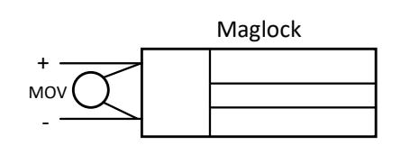
Refer to Figure A and check the placement of any suppression devices. Residual magnetism
is related to the presence of electricity (i.e., capacitance) in the lock circuit. Degaussing or dimpling the lock are not advised since it will cause unintended consequences. |
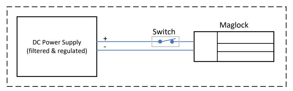
Recommended placement of switch to ensure instant release.
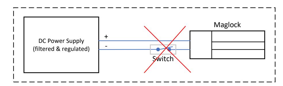
Placing the RTE switch (push plate or PIR) on the wrong leg may cause the bond to collapse more slowly than expected. Ensure the switch interrupts the positive wire and not the negative wire.
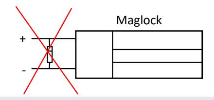
Never connect a parallel reverse diode as shown.
MAINTENANCE SCHEDULE
Company Name: _________________________________________________________
| Door Location | Date | Notes | Initial |
|---|---|---|---|
Visit: www.camdencontrols.com