CX-92S TDS Series Manual
Open the original PDF document
View PDFElectrified Locks, Relays and Timers
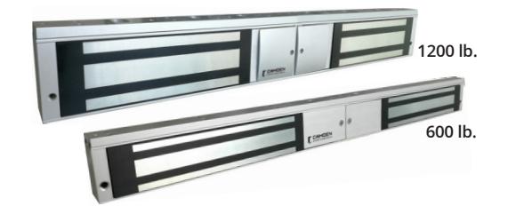
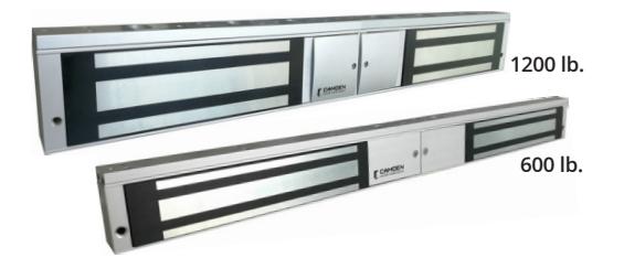
CX-92S TDS Series Magnetic Locks
INSTALLATION INSTRUCTIONS

UL 1034 / UL 294 Standard for Burglary-Resistant Electric Locking Mechanisms

ULC S533-15 Standard for Access and Egress
1. SPECIFICATIONS
| CX-92S-06-TDS | CX-92S-12-TDS | ||
|---|---|---|---|
| Static Strength |
600 lbs. x2 (Factory Tested) **
500 lbs. x2 (UL Verified) |
1200 lbs. x2 (Factory Tested) **
1000 lbs. x2 (UL Verified) |
|
| Dynamic Strength | 50 ft-lb | 70 ft-lb | |
| Voltage Input | 12/24V DC | 12/24V DC | |
| Current Draw | 510mA x 2 / 285mA x 2 | 500mA x 2 / 265mA x 2 | |
| Dimensions (Body) |
19-3/4"W x 2"H x 1-1/8"D
(500mm x 50mm x 29mm) |
21"W x 2-5/8"H x 1-9/16"D
(532mm x 67mm x 39mm) |
|
|
Dimensions
(Armature Plate) |
2 x 7-5/32"W x 1-3/4"H x 15/32"D
2 x (182mm x 44mm x 12mm) |
2 x 7-9/32"W x 13/32"H x 5/8"D
2 x (185mm x 61mm x 16.5mm) |
|
| Endurance | 250,000 | 250,000 | |
Performance Levels
- Destructive Attack = Level I
- Line Security = Level I
- Standby Power = Level I
- Endurance = Level IV
( Relay Source #2 and #3 )
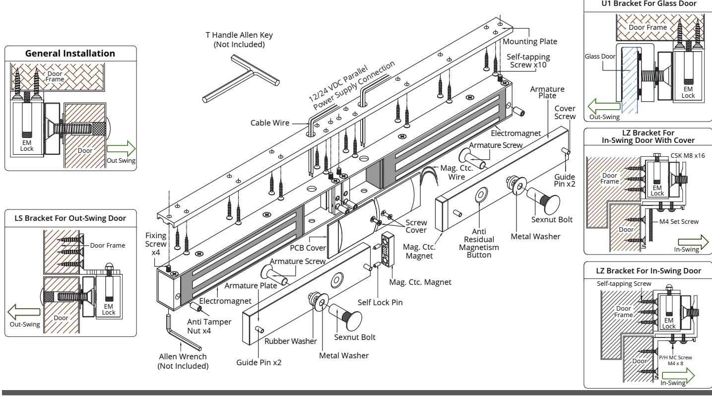
2. BASIC INSTALLATION CONCEPT & ACCESSORIES (FIGURE 1)
3. INSTALLATION
- Drill the armature plate holes in the door using the sticker template provided.
- 2. Attach the armature plate to the door with the hardware provided as per Figure 2.3.
- 3. With the door closed, mark the door frame at the edge of the armature in order to properly align the electromagnet to the armature.
-
4. Attach the mounting plate to the door frame using the self-tapping screws provided.
- Align the mounting plate with the mark from Step 3.
- 5. Insert the wires through the hole in the mounting plate and into the electromagnet unit. Attach the electromagnet unit to the mounting plate with the Allen head fixing screw.
- 6. Screw in the anti-tamper nuts to prevent unauthorized access and make sure to fully tighten the fixing screw with proper tool. A "T" Handle Allen Key.
- 7. The electromagnetic lock must be installed in accordance with the following:
- Life Safety Code ANSI / NFPA 101.
- · Local Authority having Jurisdiction.
- Manufacturer's installation instructions provided with each unit.
-
The power supply units must be mounted inside the secured or protected area.
- 8. Connect the magnetic contact wire to the door monitoring system; according to the system guides.
- 9. Typical wiring method shall be in accordance with CSA C22.1, Canadian Electrical Code, Part I, Safety Standard for Electrical Installations, Section 32.
Note:
Install in indoor dry location.
Use caution when changing factory default setting.
It is recommended to apply a light coat of silicon lubricant to the mating surface on a monthly basis to prevent rust.
NOTICE:
All models are recognized to:
UL 294 and ULC S533-15 : Standard for Access & Egress.
Models CX-91S-06 & CX-91S-12 are listed to: UL 1034, Standard for Burglary-Resistant Electric Locking Mechanism.
UL 294, Access Control System Units
** Value not verified by UL.
Remark:
All drawings shown are for illustration purpose only. Actual product may vary due to product enhancement.
4. TROUBLE SHOOTING
-
1. Sensor not functioning:
- Improper attachment of electromagnet and armature plate.
- Modification of the PCB
-
2 Door not locked:
- Incorrect wiring or no power from power supply
-
3. Reduced holding force:
- Poor contact of electromagnet and armature
- Be sure armature is loose enough that it can fully contact electromagnet along the entire length
- Mating surface is dusty or damaged
- Improper input voltage or wire size.
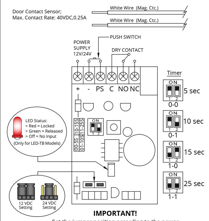
Set the jumper position according to the power input correctly before switch ON the power.
Serrures électriques, relais et minuteries

CX-92S TDS Series
Serrures magnétiques de porte
INSTRUCTIONS D'INSTALLATION

UL 1034 / UL 294 Standard for Burglary-Resistant Electric Locking Mechanisms

ULC $533-15 Standard for Access and Egress
1. PARAMÈTRES TECHNIQUES
| CX-92S-06-TDS | CX-92S-12-TDS | Niveaux de render | ||
|---|---|---|---|---|
|
Résistance
Statique |
600 lbs. x2 (Factory Tested) **
500 lbs. x2 (UL Verified) |
1200 lbs. x2 (Factory Tested) **
1000 lbs. x2 (UL Verified) |
- Attaque destructrice = ni | |
| Force Dynamique | 50 ft-lb | 70 ft-lb | - Sécurité de lignes = nive | |
| Tension | 12/24 V C.C. | 12/24 V C.C. | - Alimentation de secours | |
| Appel de courant | 510mA x 2 / 285mA x 2 | 500mA x 2/265mA x 2 | - Endurance = niveau IV | |
| Dimensions (Corps) |
19-3/4 po W x 2 po H x 1-1/8 po D
(500mm x 50mm x 29mm) |
21 po W x 2-5/8 po H x 1-9/16 po D
(532mm x 67mm x 39mm) |
( Source relais n ° 2 et n ° 3 | |
|
Dimensions
(Plaque d'armature) |
2 x 7-5/32"W x 1-3/4"H x 15/32"D
2 x (182mm x 44mm x 12mm) |
2 x 7-9/32 po W x 13/32 po H x 5/8 po D
2 x (185mm x 61mm x 16.5mm) |
||
| Endurance | 250 000 | 250 000 | ||
ment
- niveau I
- eau l
- s=niveau I
3)
2. CONCEPT D'INSTALLATION DE BASE ET ACCESSOIRES (FIGURE 1)
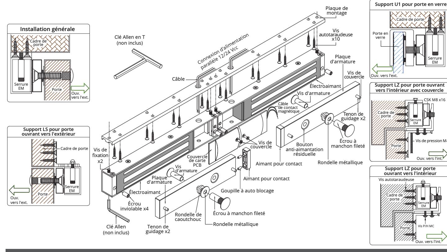
- 1. Percer les trous de la plaque d'armature dans la porte à l'aide du gabarit autocollant fourni.
- 2. Fixer la plaque d'armature à la porte avec la quincaillerie fournie selon la figure 2.3.
- 3. Avec la porte fermée, marquer le cadre de porte à l'extrémité de l'armature afin de bien aligner l'électroaimant à l'armature.
-
4. Fixer la plaque de montage au cadre de porte avec les vis autotaraudeuses fournies.
- Aligner la plaque de montage de l'étape 3.
- 5. Insérer les câbles dans le trou de la plaque de montage et dans l'unité de l'électroaimant. Fixer l'unité de l'électroaimant à la plaque de montage avec la vis la plaque de montage avec le vis Allen.
- 6. Visser les écrous inviolables afin d'empêcher l'accès non autorisé et s'assurer de bien serrer la vis de fixation avec la clé Allen en T appropriée.
- 7. Lés electroaimants installer doivent suivre:
- Code de securité ANSI / INFPA 101
- La juridiction qui a l'autorité locale.
- Le guide d'installation du fabricant qui est fourni avec chaque unité.
- Tout le cablâge devant être branché dans la zone protégée.
- 8. Connectez le fil de contact magnétique au système de surveillance de la porte; selon les guides du système.
- 9. Le système de câblage devrait suivre les règlements de CSA C22.1 les codes électriques Canadian section 1, les standards de sûreté pour les installations électriques, section 32.
Remarque:
Installez à l'intérieur dans une location sèche.
Usez de prudence si vous changez les paramètres initiaux du manufacturier.
Il est recommandé d'appliquer mensuellement une fine couche de lubrifiant à base de silicone sur la surface de contact afin de prévenir la formation de rouille.
NOTIFICATION :
Tous les modèles sont reconnus :
UL 294 et ULC S533-15: La norme pour l'accès et sortie.
Modèles CX-91S-06 et CX-91S-12 sont inscris
UL 1034, la norme pour anti-effraction électrique
Méchanisme de verouillage.
UL 294, Système de contrôle d'accès
** la valeur n'est pas vérifier par UL.
Notez :
Tous les dessins sont utiliser uniquement pour illustrer.
Le produit réel peut varier en raison de l'amélioration du produit.
3. INSTALLATION 4. DÉPANNAGE
-
1. Le détecteur ne fonctionne pas:
- Mauvaise fixation de l'électroaimant et de la plaque d'armature
- Modification de la carte de circuits imprimés
-
2. La porte ne verrouille pas:
- Mauvais branchement ou alimentation coupée de l source
-
3. La force de retenue est réduite:
- Mauvais contact de l'électroaimant et de l'armature
- S'assurer que l'armature soit suffisamment libre pour entrer complètement en contact avec l'électroaimant sur toute la longueur
- La surface de contact est poussiéreuse ou abîmée
- Mauvaise tension d'alimentation ou grosseur de câble.
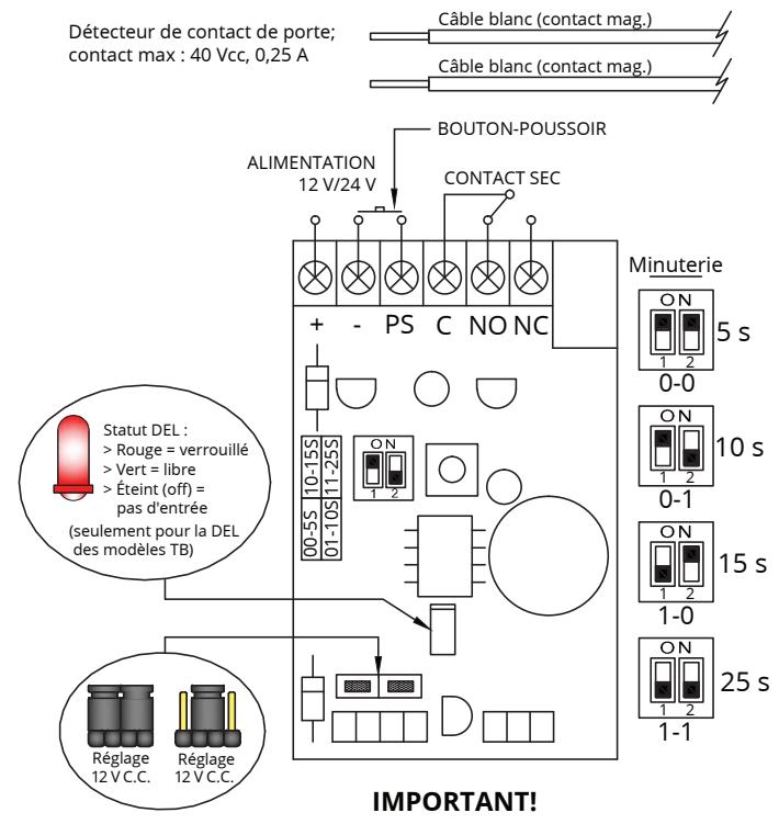
Bien régler la position du cavalier selon l'alimentation électrique avant d'activer l'interrupteur.
Visit: www.camdencontrols.com