CX-91S TDS Series Manual
Open the original PDF document
View PDFElectrified Locks, Relays and Timers
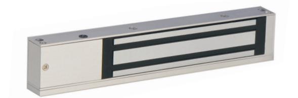
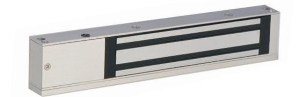
CX-91S TDS Series Magnetic Locks
INSTALLATION INSTRUCTIONS

UL 1034 / UL 294 Standard for Burglary-Resistant Electric Locking Mechanisms

ULC S533-15 Standard for Access and Egress
1. SPECIFICATIONS
| CX-91S-06-TDS | CX-91S-12-TDS | |
|---|---|---|
| Static Strength |
600 lbs. (Factory Tested) **
500 lbs. (UL Verified) |
1200 lbs. (Factory Tested) **
1000 lbs. (UL Verified) |
| Dynamic Strength | 50 ft-lb | 70 ft-lb |
| Voltage Input | 12/24V DC | 12/24V DC |
| Current Draw | 510mA/285mA | 500mA/265mA |
|
Dimensions
(Body) |
9-7/8"W x 2"H x 1"D
(250mm x 50mm x 25mm) |
10-1/2"W x 2-5/8"H x 1-1/2"D
(266mm x 67mm x 39mm) |
|
Dimensions
(Armature Plate) |
7-5/32"W x 1-3/4"H x 15/32"D
(182mm x 44mm x 12mm) |
7-9/32"W x 2-13/32"H x 5/8"D
(185mm x 61mm x 16.5mm) |
| Endurance | 250 000 | 250 000 |
Performance Levels
- Destructive Attack = Level I
- Line Security = Level I
- Standby Power = Level I
- Endurance = Level IV
( Relay Source #2 and #3 )
2. BASIC INSTALLATION CONCEPT & ACCESSORIES (FIGURE 1)
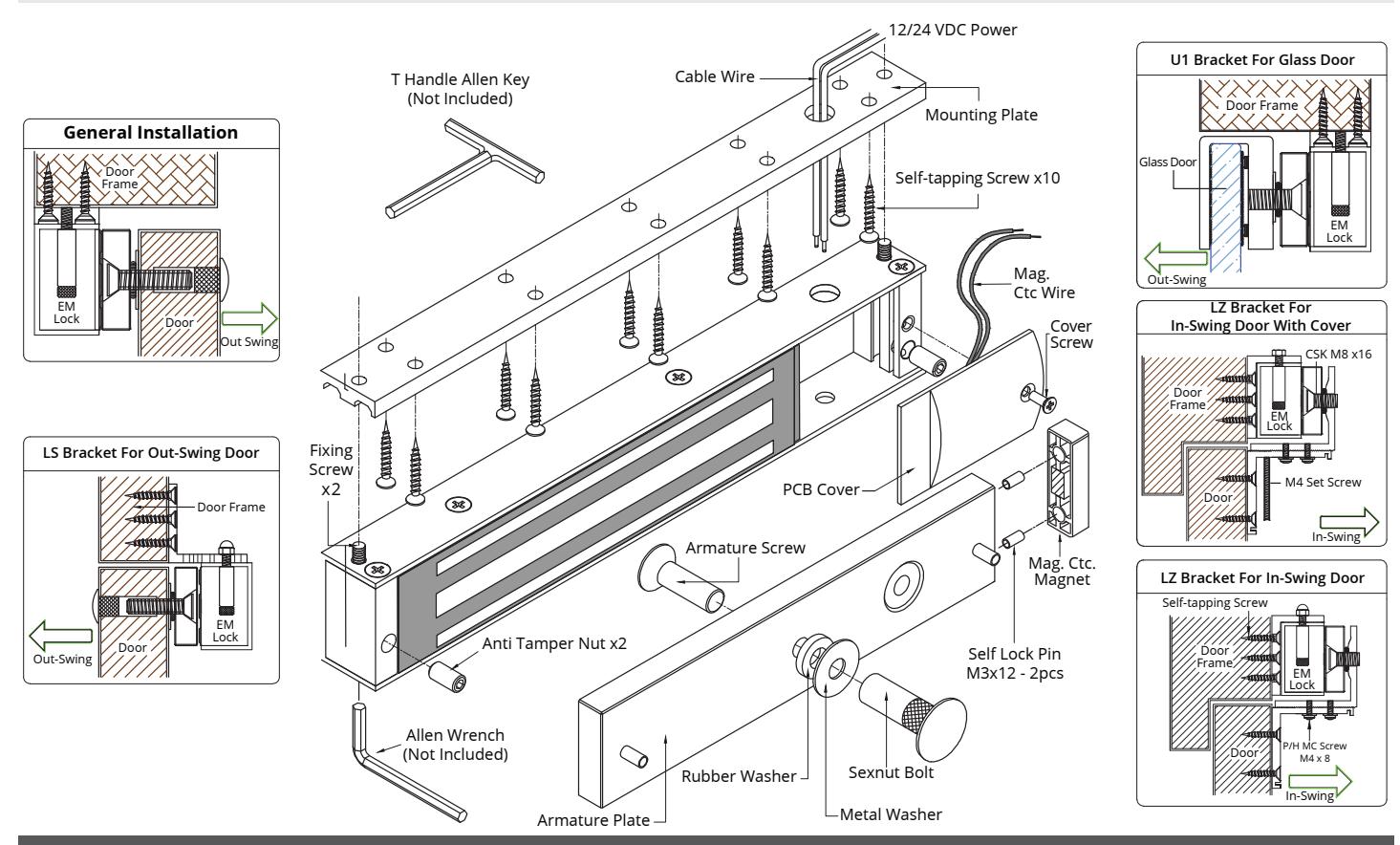
- 1. Drill the armature plate holes in the door using the sticker template provided.
- 2. Attach the armature plate to the door with the hardware provided as per Figure 2.3.
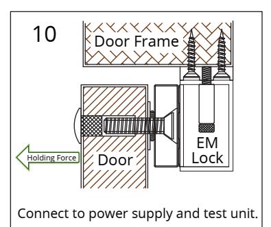
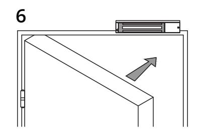
- 3. With the door closed, mark the door frame at the edge of the armature in order to properly align the electromagnet to the armature.
-
4. Attach the mounting plate to the door frame using the selftapping screws provided.
- Align the mounting plate with the mark from Step 3.
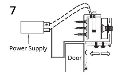
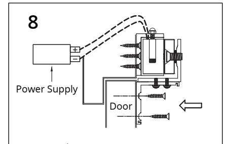
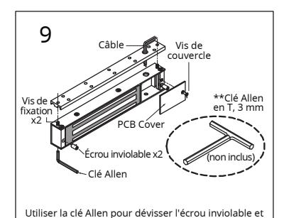
- 5. Insert the wires through the hole in the mounting plate and into the electromagnet unit. Attach the electromagnet unit to the mounting plate with the Allen head fixing screw.
- 6. Screw in the anti-tamper nuts to prevent unauthorized access and make sure to fully tighten the fixing screw with proper tool. A "T" Handle Allen Key.
- 7. The electromagnetic lock must be installed in accordance with the following :
- Life Safety Code ANSI / NFPA 101.
- Local Authority having Jurisdiction.
- Manufacturer's installation instructions provided with each unit.
-
The power supply units must be mounted inside the secured or protected area.
- 8. Typical wiring method shall be in accordance with CSA C22.1, Canadian Electrical Code, Part I, Safety Standard for Electrical Installations, Section 32.
Note:
Install in indoor dry location.
Use caution when changing factory default setting.
It is recommended to apply a light coat of silicon lubricant to the mating surface on a monthly basis to prevent rust.
Manufacturer's Instructions provided in each unit.
NOTICE:
All models are recognized to:
UL 294 and ULC S533-15 : Standard for Access & Egress.
Models CX-91S-06 & CX-91S-12 are listed to: UL 1034, Standard for Burglary-Resistant Electric Locking Mechanism.
UL 294, Access Control System Units
** Value not verified by UL.
Remark:
All drawings shown are for illustration purpose only. Actual product may vary due to product enhancement.
3. INSTALLATION 4. TROUBLE SHOOTING
- 1. Sensor not functioning:
- Improper attachment of electromagnet and armature plate.
- Modification of the PCB
-
2. Door not locked:
- Incorrect wiring or no power from power supply
-
3. Reduced holding force:
- Poor contact of electromagnet and armature
- Be sure armature is loose enough that it can fully contact electromagnet along the entire length
- Mating surface is dusty or damaged
- Improper input voltage or wire size.
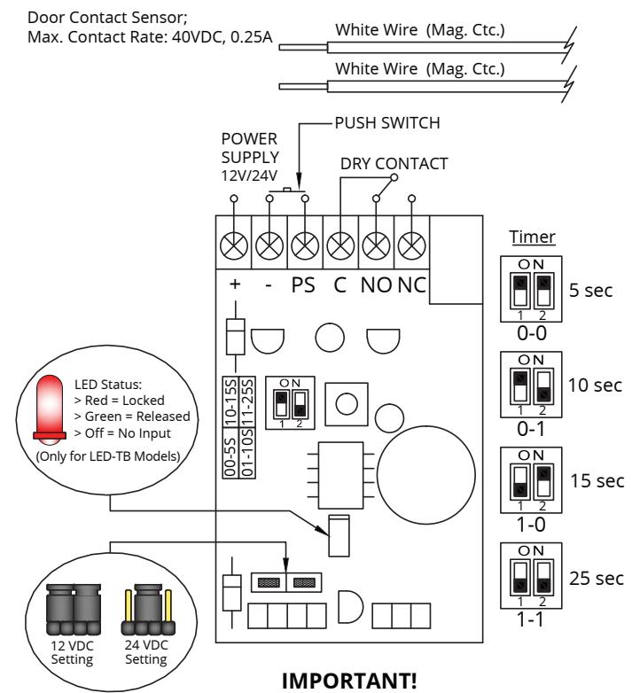
Set the jumper position according to the power input correctly before switch ON the power.
5. REGULAR INSTALLATION GUIDE (FIGURE 2)
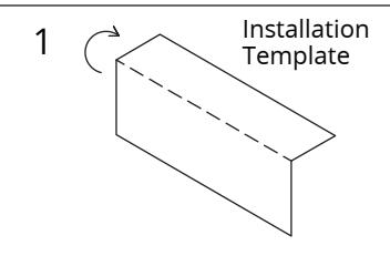
Fold the CX-91S Template along the dotted line upto 90°.
Note: Installation Template Only for In-door E.M. Lock Model 300, 600, 1200
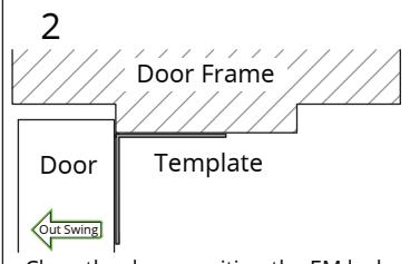
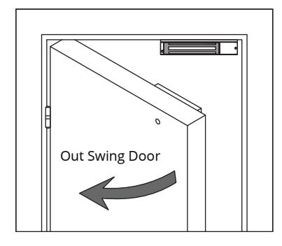
Close the door, position the EM lock mounting location as close to the door upper corner with gap 10mm.
Place the template against the door & frame and drill holes according to template indications.
Wooden Door
Door
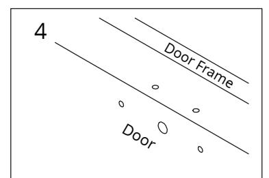
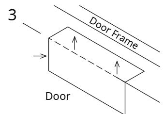
Drill 2 holes on Frame and 3 holes on door as indicated on the template.
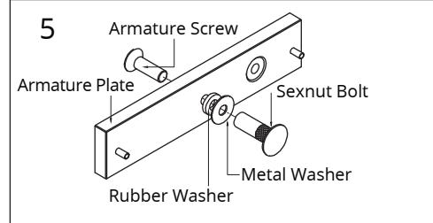
Install the Armature Plate to the door.
Note: Actual installation may varies according to door figures.
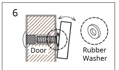
This allow the armature plate to pivot around the armature screw to compensate for door misalignment.
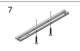
Mount the FB600 on the door frame by screw in the self tapping screw on the holes as indicated on template.
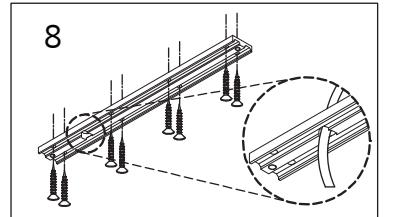
Once position is correct, screw in others screws to permanently mount the plate; and drill the wire cable access hole.
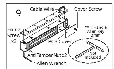
Use an Allen key wrench to unscrew the anti tamper nut and tighten the fixing screws on the mounting plate.
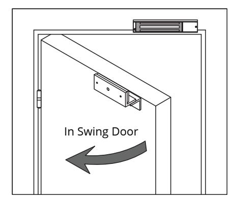
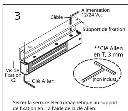
6. LZ BRACKET FOR IN-SWING DOOR INSTALLATION GUIDE (FIGURE 3)
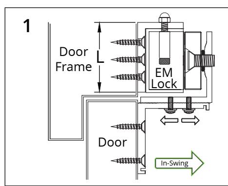
The door frame min. height value "L" is needed to accommodate the bracket Model:
| 800 LZ | 1200 LZ | |
|---|---|---|
| H | 2-1/16" | 2-7/8" |
| (52mm) | (73mm) |
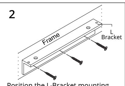
Position the L-Bracket mounting location as close to the door upper corner with gap min.10mm; make sure the door is closable.
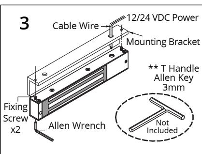
Tighten the EM Lock on the L-Bracket by using Allen Wrench.
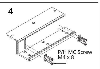
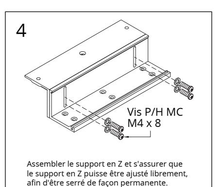
Assemble the Z-bracket and make sure the Z bracket can be adjust freely, before permanent tighten.
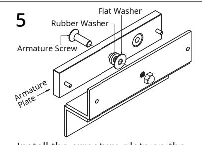
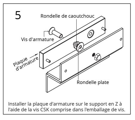
Install the armature plate on the Z-Bracket; using the CSK screw given in screw pack.
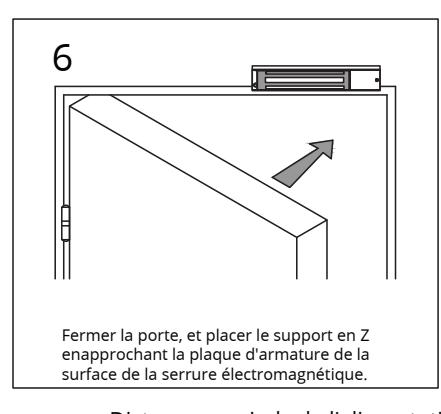
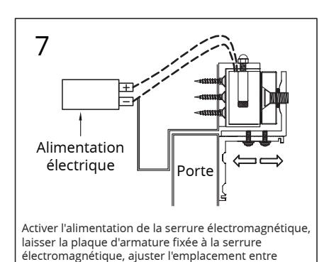
Close the door, and position the Z-Bracket by bringing the armature plate close to the EM Lock surface.
Turn On the power of EM Lock, let the armature plate attach to EM Lock; adjust the position between the Z-Bracket and the door.
Distance in feet from power supply to the furthest lock unit
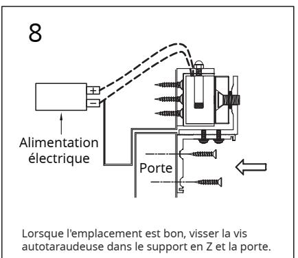
Once the position is correct, screw in the self tapping screw on the Z-Bracket to the door.
| Amps 25f 50f 75f 100f 150f 200f 250f 300f 400f 500f | 1000f | ||||||||||
|---|---|---|---|---|---|---|---|---|---|---|---|
| 0.25 | 18 | 18 18 | 18 | 18 | 16 | 16 | 14 | 14 | 12 | ||
| Minimum | 0.50 | 18 | 18 18 | 16 | 16 | 14 | 12 | ||||
| Wire Gauge | 0.75 | 18 | 18 16 | 14 | 12 | 12 | |||||
| (AWG) for | 1.00 | 18 | 16 14 | 14 | 12 | ||||||
| 12VDC | 1.50 | 18 | 14 12 | 12 | |||||||
| 2.00 | 16 | 14 12 | |||||||||
| Amps 25f 50f 75f 100f 150f 200f 250f 300f 400f 500f | 1000f | ||||||||||
| 0.25 | 18 | 18 18 | 18 | 18 | 18 | 18 | 18 | 16 | 16 | 16 | |
| Minimum | 0.50 | 18 | 18 18 | 18 | 18 | 16 | 16 | 14 | 14 | 12 | |
| Wire Gauge | 0.75 | 18 | 18 18 | 18 | 16 | 14 | 14 | 12 | 12 | ||
| (AWG) for | 1.00 | 18 | 18 16 | 16 | 14 | 14 | 12 | 12 | |||
| 24VDC | 1.50 | 18 | 18 16 | 14 | 14 | 12 |

Serrures électriques, relais et minuteries

CX-91S TDS Series
Serrures magnétiques de porte
INSTRUCTIONS D'INSTALLATION

UL 1034 / UL 294 Standard for Burglary-Resistant Electric Locking Mechanisms

ULC S533-15 Standard for Access and Egress
1. PARAMÈTRES TECHNIQUES
| CX-91S-06-TDS | CX-91S-12-TDS | |
|---|---|---|
| Static Strength |
600 lbs. (Factory Tested) **
500 lbs. (UL Verified) |
1200 lbs. (Factory Tested) **
1000 lbs. (UL Verified) |
| Force Dynamique | 50 ft-lb | 70 ft-lb |
| Tension | 12/24 V C.C. | 12/24 V C.C. |
| Appel de courant | 510mA/285mA | 500mA/265mA |
| Dimensions (Corps) |
9-7/8 po W x 2 po H x 1 po D
(250 mm x 50 mm x 25 mm) |
10-1/2 po W x 2-5/8 po H x 1-1/2 po D
(266 mm x 67 mm x 39 mm) |
|
Dimensions
(Plaque d'armature) |
7-5/32 po W x 1-3/4 po H x 15/32 po D
(182 mm x 44 mm x 12 mm) |
7-9/32 po W x 2-13/32 po H x 5/8 po D
(185 mm x 61 mm x 16.5 mm) |
| Endurance | 250 000 | 250 000 |
Niveaux de rendement
- Attaque destructrice = niveau I
- Sécurité de lignes = niveau I
- Alimentation de secours = niveau I
- Endurance = niveau IV
(Source relais n ° 2 et n ° 3)
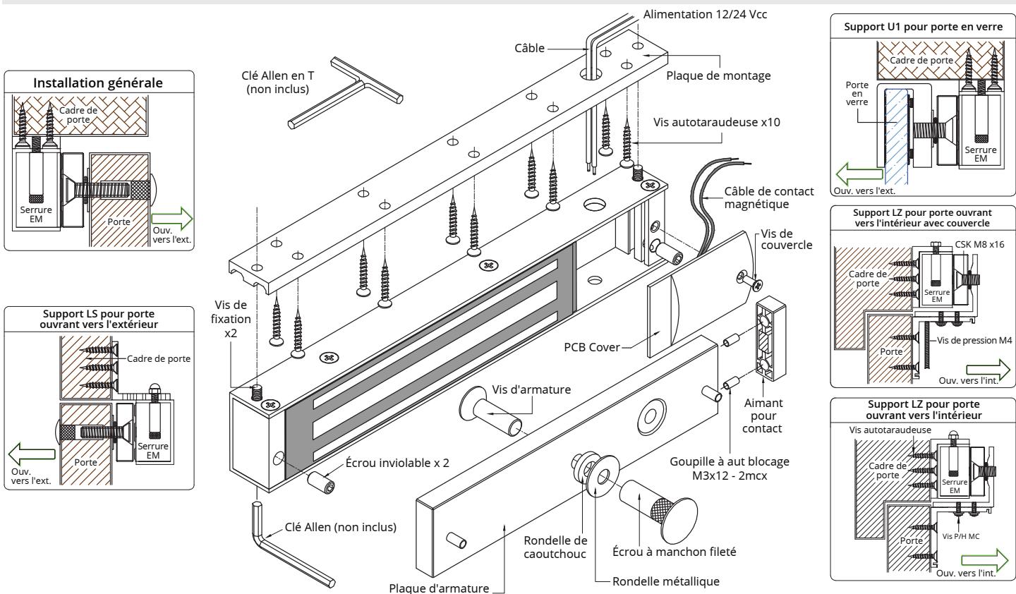
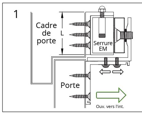
2. CONCEPT D'INSTALLATION DE BASE ET ACCESSOIRES (FIGURE 1)
3. INSTALLATION 4. DÉPANNAGE
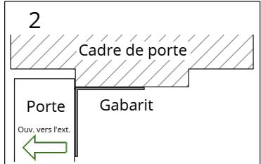
- 1. Percer les trous de la plaque d'armature dans la porte à l'aide du gabarit autocollant fourni.
- 2. Fixer la plaque d'armature à la porte avec la quincaillerie fournie selon la figure 2.3.
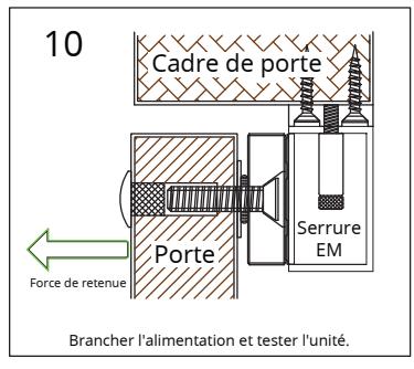
- 3. Avec la porte fermée, marquer le cadre de porte à l'extrémité de l'armature afin de bien aligner l'électroaimant à l'armature.
-
4. Fixer la plaque de montage au cadre de porte avec les vis autotaraudeuses fournies.
- Aligner la plaque de montage de l'étape 3.
- 5. Insérer les câbles dans le trou de la plaque de montage et dans l'unité de l'électroaimant. Fixer l'unité de l'électroaimant à la plaque de montage avec la vis la plaque de montage avec le vis Allen.
- 6. Visser les écrous inviolables afin d'empêcher l'accès non autorisé et s'assurer de bien serrer la vis de fixation avec la clé Allen en T appropriée.
- 7. Lés electroaimants installer doivent suivre:
- Code de securité ANSI / INFPA 101
- La juridiction qui a l'autorité locale.
- Le guide d'installation du fabricant qui est fourni avec chaque unité.
- Tout le cablâge devant être branché dans la zone protégée.
- 8. Connectez le fil de contact magnétique au système de surveillance de la porte; selon les guides du système.
- 9. Le système de câblage devrait suivre les règlements de CSA C22.1 les codes électriques Canadian section 1, les standards de sûreté pour les installations électriques, section 32.
Remarque:
Installez à l'intérieur dans une location sèche.
Usez de prudence si vous changez les paramètres initiaux du manufacturier.
Il est recommandé d'appliquer mensuellement une fine couche de lubrifiant à base de silicone sur la surface de contact afin de prévenir la formation de rouille.
NOTIFICATION :
Tous les modèles sont reconnus :
UL 294 et ULC S533-15: La norme pour l'accès et sortie.
Modèles CX-91S-06 et CX-91S-12 sont inscris
UL 1034, la norme pour anti-effraction électrique
Méchanisme de verouillage.
UL 294, Système de contrôle d'accès
** la valeur n'est pas vérifier par UL.
Notez :
Tous les dessins sont utiliser uniquement pour illustrer.
Le produit réel peut varier en raison de l'amélioration du produit.
-
1. Le détecteur ne fonctionne pas:
- Mauvaise fixation de l'électroaimant et de la plaque d'armature
- Modification de la carte de circuits imprimés
-
2. La porte ne verrouille pas:
- Mauvais branchement ou alimentation coupée de l source
-
3. La force de retenue est réduite:
- Mauvais contact de l'électroaimant et de l'armature
- S'assurer que l'armature soit suffisamment libre pour entrer complètement en contact avec l'électroaimant sur toute la longueur
- La surface de contact est poussiéreuse ou abîmée
- Mauvaise tension d'alimentation ou grosseur de câble.
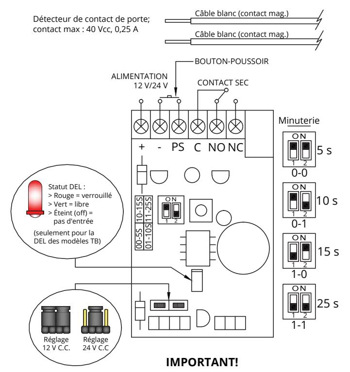
Bien régler la position du cavalier selon l'alimentation électrique avant d'activer l'interrupteur.
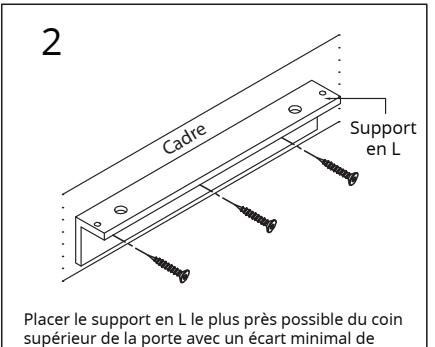
5. GUIDE D'INSTALLATION RÉGULIÈRE (FIGURE 2)
Figure
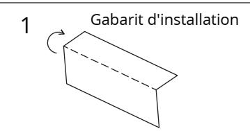
Plier le gabarit CX-91S le long de la ligne pointillée pour obtenir un angle de 90o. Remarque : Le gabarit d'installation convient seulement pour les modèles de serrures électromagnétiques pour l'intérieur 300, 600,et 1200.
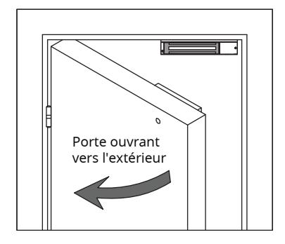
Fermer la porte, déterminer l'emplacement du montage de la serrure électromagnétique le plusprès possible du coin supérieur de la porte avec un écart de 10 mm.
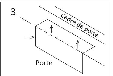
Placer le gabarit contre la porte et le cadre et percer des trous selon les indications du gabarit.
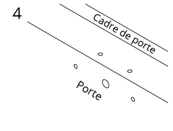
Percer 2 trous dans le cadre et 3 trous dans la porte selon les indications du gabarit.
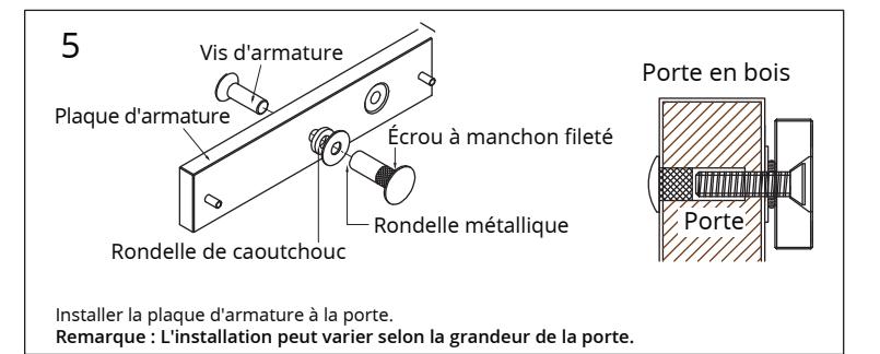
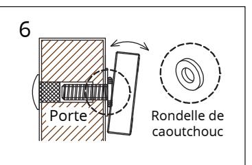
Ceci permet à la plaque d'armature de pivoter autour de la vis d'armature afin de compenser tout mauvais alignement de la porte.
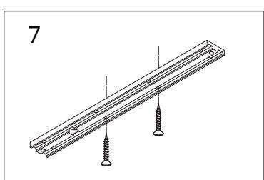
Fixer le FB600 au cadre de porte à l'aide de vis autotaraudeuses insérées dans les trous indiqués sur le gabarit.
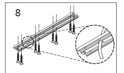
Lorsque la position est bonne, visser les autres vis afin de fixer la plaque de façon permanente, et percer le trou d'accès du câble.
serrer les vis de fixation sur la plaque de montage.
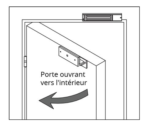
6. GUIDE D'INSTALLATION DU SUPPORT LZ POUR PORTE OUVRANT VERS L'INTÉRIEUR (FIGURE 3)
Figure
La valeur L de hauteur minimale du cadre de porte est nécessaire pour le modèle de support :
| 800 LZ | 1200 LZ | |
|---|---|---|
| H | 2-1/16" | 2-7/8" |
| (52mm) | (73mm) |
10 mm, s'assurer que la porte puisse fermer.
le support en Z et la porte.
Calibre de fil A 25f 50f 75f 100f 150f 200f 250f 300f 400f 500f 0.25 18 18 18 18 18 16 16 14 14 12 18 18 18 16 16 14 12 1000f Distance en pieds de l'alimentation jusqu'à la serrure la plus loin
minimal (AWG) pour 12 Vcc 0.75 1.00 1.50 2.00 18 18 16 14 12 12 18 16 14 14 12 18 14 12 12 16 14 12 Amps 25f 50f 75f 100f 150f 200f 250f 300f 400f 500f 0.25 18 0.50 0.75 1.00 1.50 2.00 18 18 18 18 18 18 18 16 16 18 18 18 18 18 16 16 18 18 18 18 16 14 18 18 16 16 14 18 18 16 14 16 16 14 1000f 16 14 14 12 14 12 12 14 12 12 14 12 14 12 Calibre de fil minimal (AWG) pour 24 Vcc

Call: 1.877.226.3369 / 905.366.3377 Visit: www.camdencontrols.com

Fichier: CX-91S-TDS-Series_Manual_R4.indd
Rev.: 11/12/20 Pièce no.: 40-82B217-F