CX-1000-77 Manual
Open the original PDF document
View PDF


CX-1000/77 Timer (MaxiMinder)
INSTALLATION INSTRUCTIONS
CX-1000/77
1. GENERAL DESCRIPTION
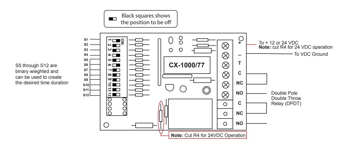
The CX-1000/77 timer can run on either 12 or 24 VDC and has an adjustable activation time of 1 second to 4 hours in duration. The duration time is adjusted by setting the timing dip switches to the desired time needed to trigger its doublepole double throw (DPDT) relay. It also can be used in the delay mode which will wait for the set timing to expire then activate the output until the trigger is removed. The timer is activated by a normally open momentary negative trigger (trigger input to ground) but can also be configured as a normally closed momentary positive trigger.
2. SPECIFICATIONS
| Power Input |
12 or 24 VDC
(cut R4 for 24VDC operation) |
|---|---|
| Output Contact Rating | 12/24 VDC @ 4 amps |
| Current Draw | 12mA/Idle, 60mA/Peak |
3. APPLICATION
Extended Duration: Tennis courts, parking lots (to control lighting), school open house or event day (keep main doors unlocked for visitors), paid usage of a machine (washers/ dryers, spray and wash/vacuums for cars), Door Operator trigger (maintain an extended open time), bypass or shunt an alarm system door contact (during moving day or repairs).
Delay on Activation: Door Held Open alarm (alarm or sounder triggered if the door is not closed within a specified amount of time), Delayed Egress (provide an extended trigger to then unlock a door).
4. OPERATION AT A GLANCE
Timed Output Mode (Relay triggers for the set amount of time)
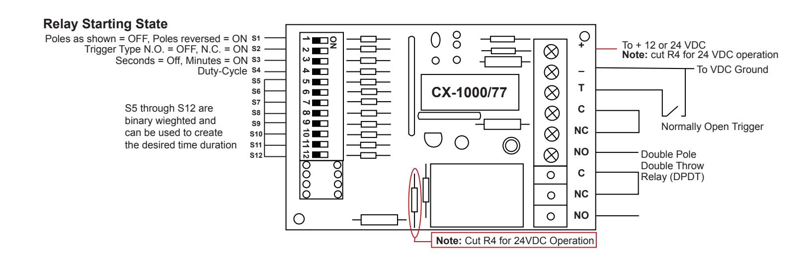
Once the timer has been set for the desired mode and timing, a normally open momentary negative trigger on the "T" terminal to ground (Gnd) will turn on the relay and run for the duration set by the dip switches then turn off. The timer can have its trigger configuration changed from a normally open trigger going closed or to a normally closed trigger going to an open by changing the state of S2.
Example: You want to bypass (shunt) an Alarm System door contact for 10 seconds. You will set the switches for a 10 second total and when the "T" terminal is taken low (Gnd) it will turn on the relay for 10 seconds then turn off.
Delay on Release Mode (Relay triggers after the set amount of time then turns off when the trigger is removed)
Note: this option is triggered by powering up the CX-1000/77 timer and not from the "T" terminal. Applying power to the timer is the trigger for this option.
Once power has been applied for the delay on activation desired time the relay will turn on. The relay will turn off when power is removed. This action will happen again once the power has been applied for longer than the desired delay on activation time. Then when the trigger is removed the relay will turn off.
Example: If you want a door operator to open 4 seconds after a trigger and stay open for 4 seconds then you will need to set the trigger from the controlling device (device providing power to the CX-1000/77 timer) to 8 seconds. When triggered for 4 seconds the relay will turn on and 4 seconds later when the trigger is removed the relay will turn off.
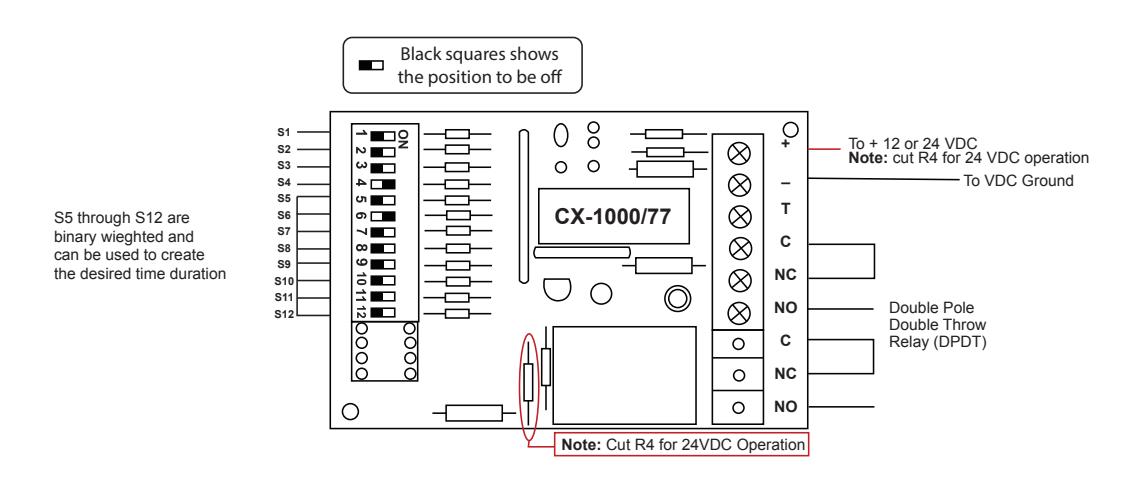
5. CONFIGURATION:
Layout of the Dip Switches
- S1 The starting state of the relay. SW1 OFF = relay poles are as shown. SW1 ON = relay poles are reversed.
- S2 The type of trigger to be used. SW2 OFF = normally open. SW2 ON = normally closed.
- S3 If the timing will be in seconds or minutes. SW3 OFF = seconds. SW3 ON = minutes.
- S4 If duty-cycle is set or not. S4 OFF = no duty-cycle. SW4 ON = yes duty-cycle. Duty-Cycle = same time on and off.
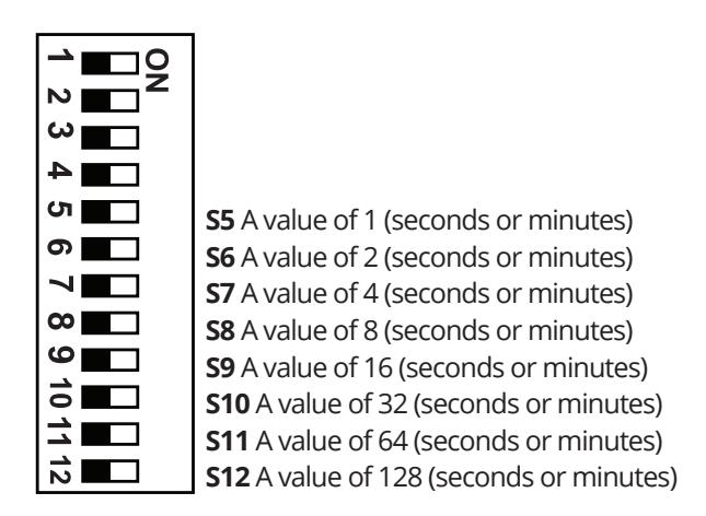
Note: The values of SW5 through S12 will be based on whether S3 is set to OFF for seconds or ON for minutes. Set the dip switches for the desired time.
Example of a setting of 10 seconds: S3 = OFF, SW6 & SW8 = ON.
6. APPLICATIONS
1) Output Activation Timed (typical)
Set the output to activate for the set timing upon receiving a trigger and stay on for 30 seconds.
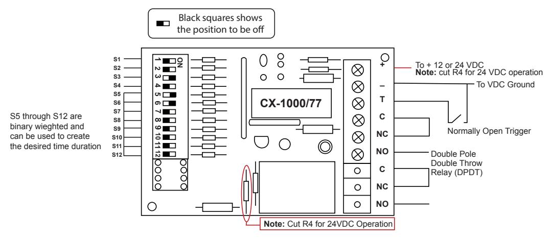
Application 1) Trigger the output to come on for 3 minutes
To set the timer to be triggered for 3 minutes S3, S5, & S6 are put on
S3 sets the timing in minutes
S5 carries a binary weight of 1
S6 carries a binary weight of 3
S5 & S6 combined carry a binary weight of 3
When the trigger terminal (T) is brought low (Gnd) the timer will activate its output for 3 minutes.
2) Output Activation Delayed (waits to trigger)
Set the output to wait (delay) for 30 seconds upon power-up then turn off when powered is removed.
Application 2) When powered up the relay will come on after the 3 minute delay (T terminal is not used)
To set the timer to wait (delay) for 3 minutes before the relay activation S1, S3, S5, S6 are set to the ON position.
S1 sets the timer to wait until the specified time has expired to activate the relat then turns off when the power is removed.
S3 sets the timing in minutes
S5 carries a binary weight of 1
S6 carries a binary weight of 2
S5 & S6 combined carry a binary weight of 3
When power is applied to the timer it will start the 3 minute timing cycle then activate the relay until power is removed. Powering up the timer is the trigger for this application.
3) Output Latching (maintained)
Set the output to latch (stay-on) until triggered to turn off.
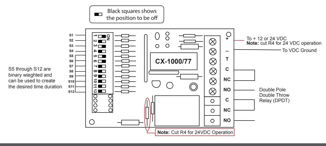
Application 3) Latching relay (maintained) when powered
To configure the timer to latch (stay on) when powered up and to reset the latch (turn off) set all the dip switches to the off position. When the timer is powered up the relay will turn on and stay on until power is removed. In this application the trigger is the power being applied and removed.
4) Output Latching Delayed (waits for timing to expire before activation)
Application 4) Output Latching Delayed (waits for timing to expire before activation)
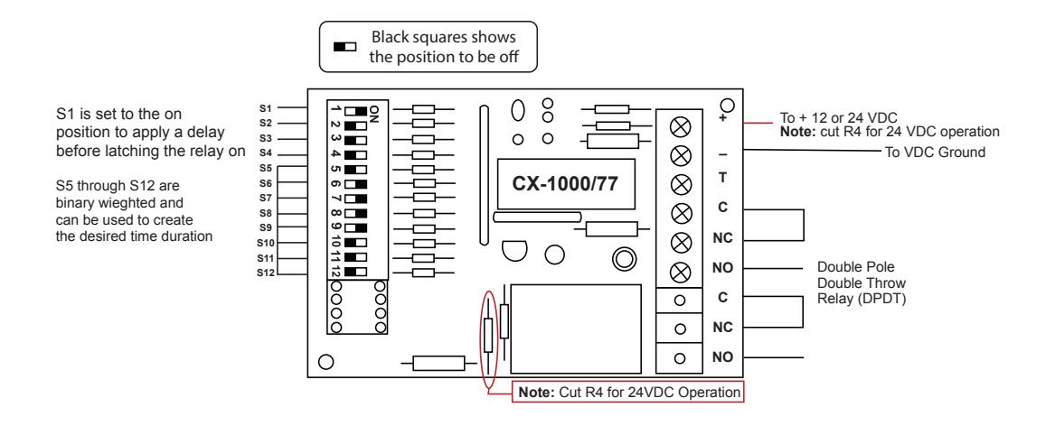
To configure the timer to delay its latching output for the specified time set switch 1 to the on position. Switches S5 through S12 can be set for the specified time needed before the relay activates and stays on. Unlatching (reset relay back to off) is done by removing power to the timer.
In the drawing below S1 is in the on position (delay relay activation) and S6, S7, S8 & S9 are in on position adding up to 30 seconds. When power is applied to the timer it will wait (delay relay activation) for 30 seconds then latch (stay on) the relay in the on positin until power is removed from the timer.
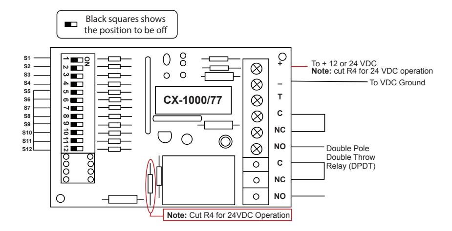
5) Flasher (duty cycle with no delay)
Application 5) Flasher (duty cycle with no delay)
To configure the timer to start cycling its relay on and off set S4 to the on position. Then set S5 through S12 for the specified amount of time the relay needs to be set for its on and off times. Apply power to the timer and the relay will activate for the specified on time then for the specified off time. This will continue to repeat until the power (trigger) is removed.
In this application the timer will flash/duty-cycle on for 2 seconds and off for 2 seconds. Set S4 to enable duty-cycle and set S6 to the on postion for two seconds. Apply power.
6) Flasher (duty cycle with delay before activation)
To configure the timer to wait (delay) to start set S1 to the on position then set the specified time for on and off times to cycle on and off.
Use S5 through S12 to set the desired on and off times for the flasher/duty cycle and for the initial delay before starting. In this application S1 is set on (delay on activation) an S4 is set on for the duty cycle option. S6 is set to on for 2 seconds which the delay and the duty cycle will be using.