CV-550SPK V3 Reference Manual
Open the original PDF document
View PDF

CV-550SPK v3 Reference Manual
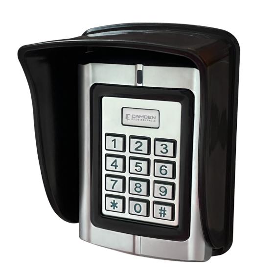
TABLE OF CONTENTS
| Page Numbers | |
|---|---|
| 1. Overview | |
| 1.1 Introduction | |
| 1.2 Function features | |
| 1.3 Keypad exterior features | 4 - |
| 1.4 Technical parameters | |
| 1.5 Applicable models | 5 - |
| 2. Installation, wiring and debugging | - 6 - |
| 2.1 Installation | 6 - |
| 2.2 Wiring | 6 - |
| 2.3 Commissioning the system | |
| 3. Getting Started | 12 - |
| 3.1 Enter management menu operation mode | 13 - |
| 3.2 Change admin password | 13 - |
| 3.3 Set controller to single-door mode | 13 - |
| 3.4 Set door opening time to 2S | 13 - |
| 3.5 Add user card | 13 - |
| 3.6 Add user PIN | 13 - |
| 3.7 Exit management menu operation mode | 14 - |
| 3.8 User open door | 14 - |
| 4. Basic Functions | 14 - |
| 4.1 Management menu operations | 14 - |
| 4.1.1 Change admin password | 14 - |
| 4.1.2 Set or delete super-open-password | 14 - |
| 4.1.3 Set admin card | 14 - |
| 4.1.4 Delete admin card | 15 - |
| 4.1.5 Set keypad mode | 15 - |
| 4.1.6 Limits types of reading card | 15 - |
| 4.1.7 Restore to default settings | 15 - |
| 4.1.8 Add user | 16 - |
| 4.1.9 Delete user | 16 - |
| 4.1.10 Set open door methods | 17 - |
| 4.1.11 Set multi-card to open door | 17 - |
| 4.1.12 Set lock working mode | 17 - |
| 4.1.13 Set limits user mode | 17 - |
| 4.1.14 Set open-time | |
| 4.1.15 Door ajar alarm period | |
| 4.1.16 Set alarm-time | |
| 4.1.17 Set tampering alarm function | |
| 4.1.18 Set alarm or doorbell output function | |
| 4.1.19 Set error lock out function |
| Page Numbers | |
|---|---|
| 4.1.20 Set LED indicator light mode | 18 - |
| 4.1.21 Adjust the brightness of the normally bright red indicator | 18 - |
| 4.1.22 Set key backlit mode | 19 - |
| 4.1.23 Adjust brightness of key backlit | 19 - |
| 4.1.24 Set buzzer mode | 19 - |
| 4.1.25 Adjust key volume | 19 - |
| 4.1.26 Set the # key whether it can be used doorbell key | 19 - |
| 4.1.27 Set doorbell key mode | 19 - |
| 4.1.28 Set reader output format | 20 - |
| 4.2 Admin card or PIN operation | 22 - |
| 4.2.1 Set-card operation | 22 - |
| 4.2.2 Add-card operation | 22 - |
| 4.2.3 Delete-card operation | 22 - |
| 4.2.4 Super-open-card operation | 22 - |
| 4.2.5 Super-open-password operation | 22 - |
| 4.2.6 Anti-duress-card operation | 22 - |
| 4.2.7 Authorization-card operation | 23 - |
| 4.2.8 Normal-open-card operation | 23 - |
| 4.3 Users operation | 23 - |
| 4.3.1 Get user card or PIN | 23 - |
| 4.3.2 Change user PIN | 23 - |
| 4.3.3 User open door | 23 - |
| 4.4 Other operations | - 24 - |
| 4.4.1 Cancel alarming | 24 - |
| 4.4.2 Admin password initialization | 24 - |
| 4.4.3 Restore factory settings | 24 - |
| 4.5 Operation characteristics in different Keypad modes | - 24 - |
| 4.5.1 Operation characteristics in reader mode | 24 - |
| 4.5.2 Operation characteristics in single-door mode | 25 - |
| 4.5.3 Operation characteristics in interlock mode | |
| 4.5.4 Operation characteristics in demo mode | 25 - |
| 5. Management menu summary table | 25 - |
| 5.1 Reader mode management menu summary table | - 25 - |
| 5.2 Single-door mode management menu summary table | - 27 - |
| 5.3 Interlock mode management menu summary table | - 30 - |
| 5.4 Demo mode management menu summary table | 30 - |
| 6. Precautions in use | 31 - |
| 7. Common troubleshooting | 31 - |
| 8. Compatible peripherals | 32 - |
1. OVERVIEW
1.1 Introduction
This version of keypad uses the new 32-bit microcontroller ARM core design with enhanced beneficial functions. It's a new generation of multi-function access controller with a card reader mode, single-door mode, interlock mode, Demo mode etc. All of them could be widely used in office buildings, homes, schools, condominium, apartments, factories, fenced in yards and other places.
1.2 Function features
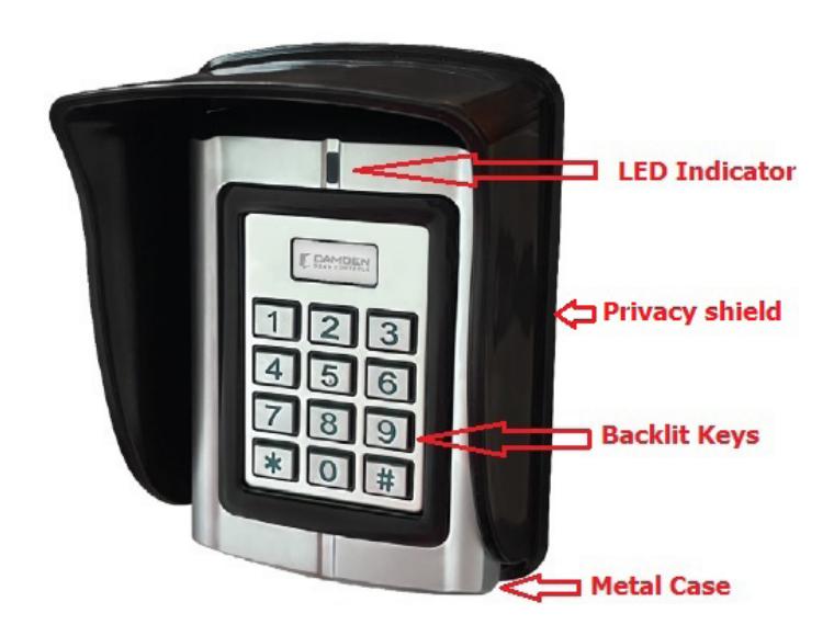
- Built-in reader reads 125 kHz proximity credentials (EM& HID format).
- Vandal-resistant metal backlit keypad.
- Single-door controller can be set to Reader mode, Interlock mode and demo mode.
- Reader mode Wiegand output is configurable by the installer.
- Authentication by Card and PIN or Multi-cards to open the door.
- Administrator Super-open-card and Super-open-password to open door.
- Convenient administrator Add-card, Delete-card, Anti-duress-card, Authorization-card, and Normal-open card operation.
- Quick access to the management menu using admin password card feature.
- User card capacity up to 20,000, the admin programming card capacity up to 21.
- Quick access to the management menu using Set-card operation
- Doorbell button available using the "#" key once it is configured.
- In Reader mode, the keypad red and green LED indicators can be controlled externally.
- Innovative infrared tampering detection technology. The keypad can alarm 24/7 and it will not be affected by ambient light.
- Door Strike or maglock controlled by output relay contacts (NO, NC, COM).
- Alarm and doorbell signal output by MOS and it can be the driver of an alarm device or a doorbell.
1.3 Keypad exterior features
1.4 Technical parameters
- Working Voltage: AC/DC10-28V
- Standby current: ≤35mA (Input DC12V)
- Operating current: ≤100mA (Input DC12V)
- Working temperature: -40 °F + 140 °F ( -40 to 60 °C)
- Working humidity: 0-95%
- Lock signal relay contact current: ≤1A
- Alarm (or doorbell) signal MOS output current: ≤1A
- Distance of reading EM card: ≤ 2 inches (5 cm)
- Distance of reading HID card: ≤ 2 inches (5 cm)
1.5 Applicable models
This user manual applies to the following items:
- 1. CM-550SPK v3 Stand Alone Keypad & Reader with 12 colored wire leads.
- 2. Rain /Privacy Shield for the keypad.
2. INSTALLATION, WIRING AND DEBUGGING
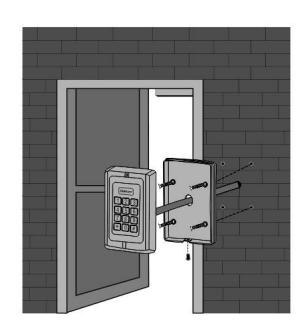
2.1 Installation
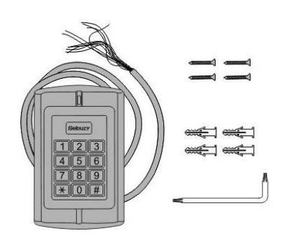
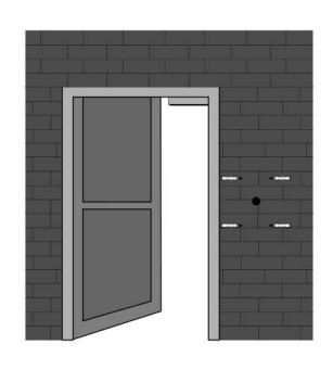
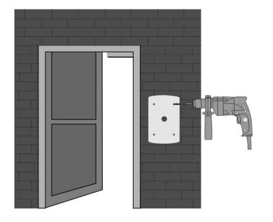
Using the Torx screwdriver remove the security fastening screw at the bottom of the device. Take off the bottom case and use it to mark the position on the wall for the mounting holes. Use a drill to open a corresponding hole in the wall. The backplate marks an outlet hole with a diameter greater than ¼" (8mm) and four plastic wall plugs holes with a diameter of ¼" (6mm). Use a Phillips screwdriver to secure the backplate to the four matching plastic wall plugs with the four matching self-taping screws.
2.2 Wiring
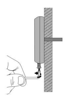
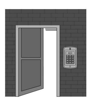
Refer to the selected wiring diagram, cut the wire to the right length and cut off the excess feeding the cable through the wall or into the backbox. Connect the remaining keypad wires as shown on the wiring diagram. Be careful not to connect the wrong wires or short circuit, otherwise permanent damage to the keypad may occur. After checking, power on for a short time, confirm the indicator light is normal and the buzzer beeps once. Otherwise, power off immediately and recheck the wiring properly. If all is well, secure the keypad onto the backplate on the wall and tighten it with the security screw as below:
The product wiring colors and functions are shown in the following table:
| Color | Symbol | Functions |
|---|---|---|
|
Light
green |
AC2 | One of the AC power supply terminal. |
| Blue | NO | Normal open terminal of Relay |
| Purple | COM | Common terminal of Relay |
| Orange | NC | Normal close terminal of Relay |
| Grey | ALARM(BELL) | Alarm (or doorbell) signal MOS drain output |
| Yellow | OPEN(BEEP) | Exit button input (or external control input of buzzer) |
| Brown | D_IN(LED_G) | Door contact input (or external control input of green LED) |
| Red | +12V(AC1) | Positive DC power (or another terminal of AC power supply) |
|---|---|---|
| Black | GND | Ground |
| Green | D0 | Wiegand signal, D0 input or output (or RS232-TTL signal output: Tx) |
| White | D1 | Wiegand signal, D1 input or output (or RS232-TTL signal input : Rx) |
| Pink | D_IN2(LED_R) | External control input of red LED |
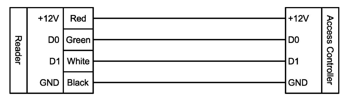
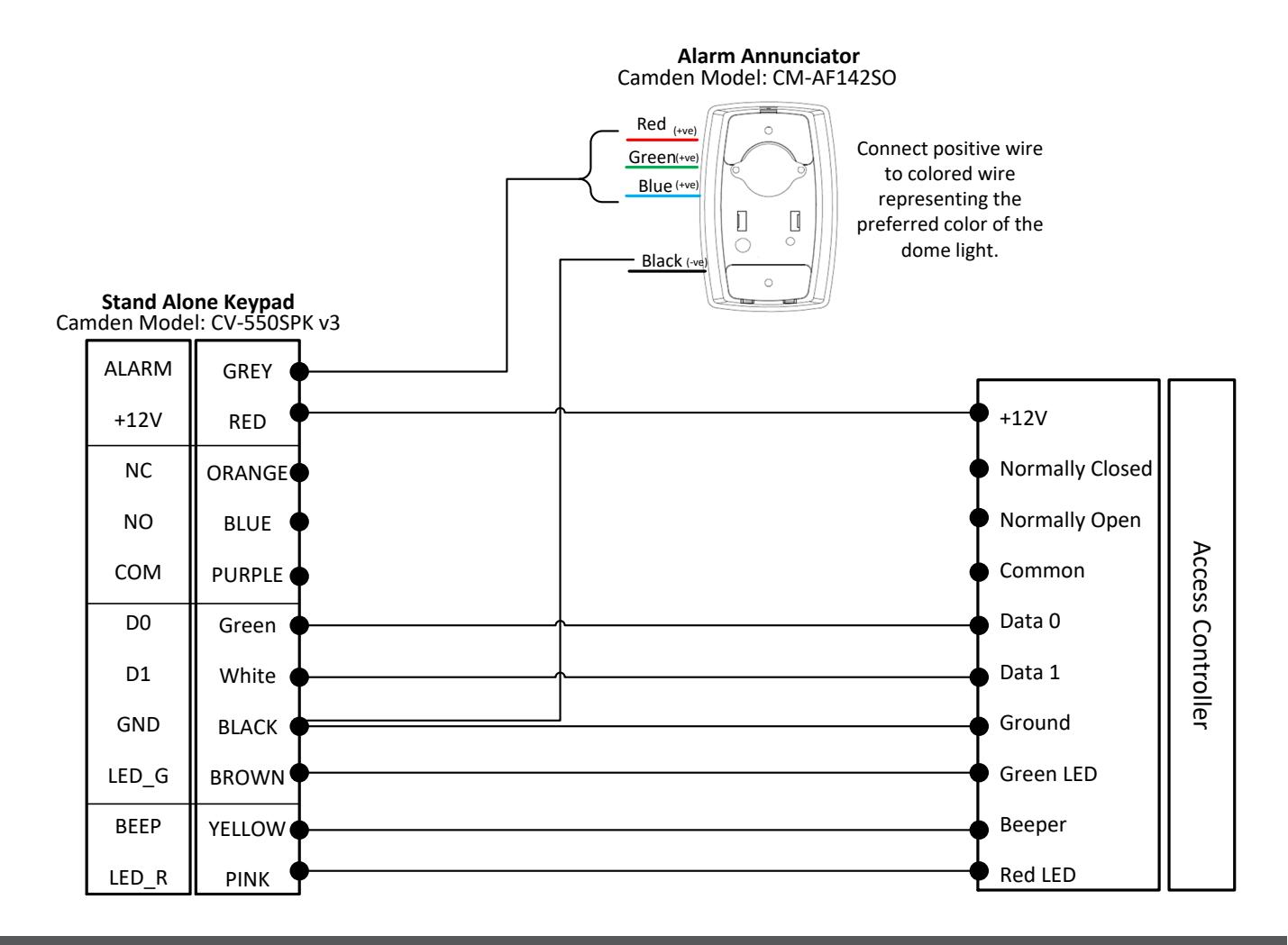
Wiring the CV‐550SPK V3 to an ACCESS CONTROLLER Must be configured for reader mode
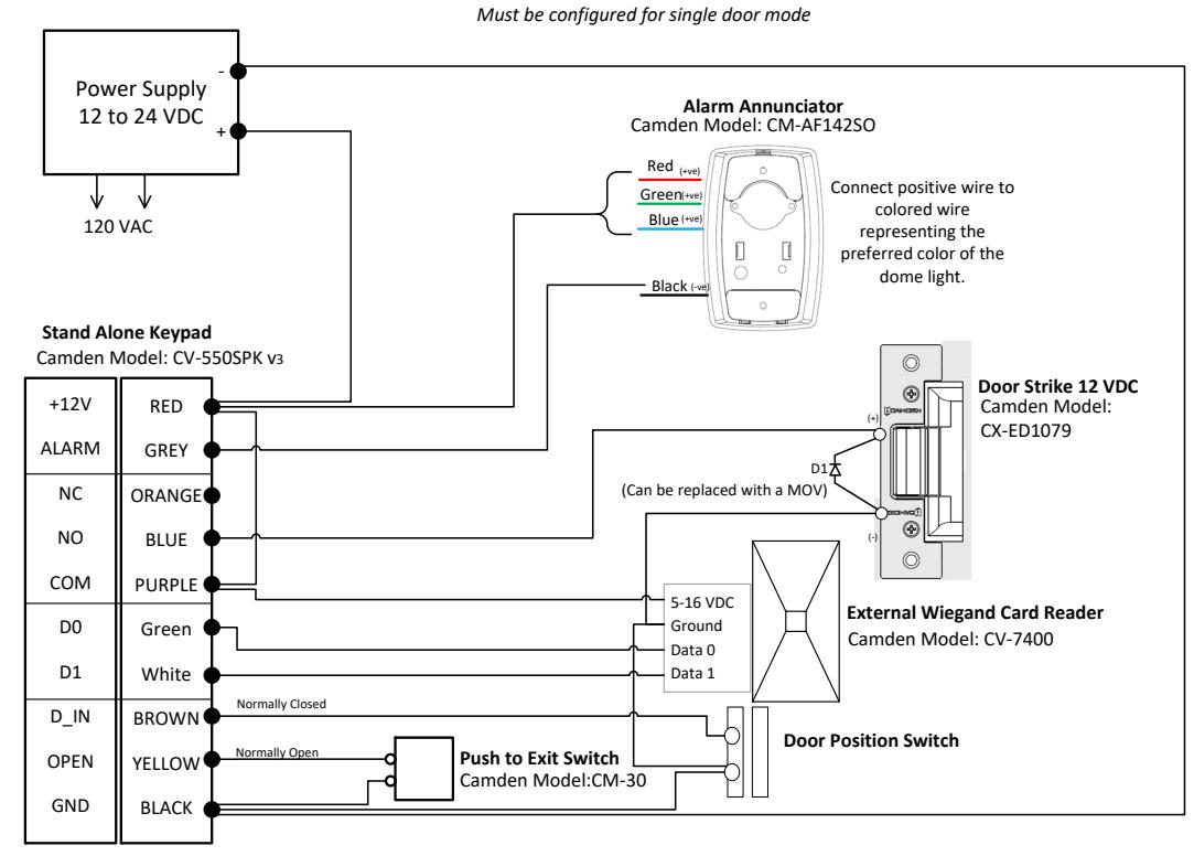
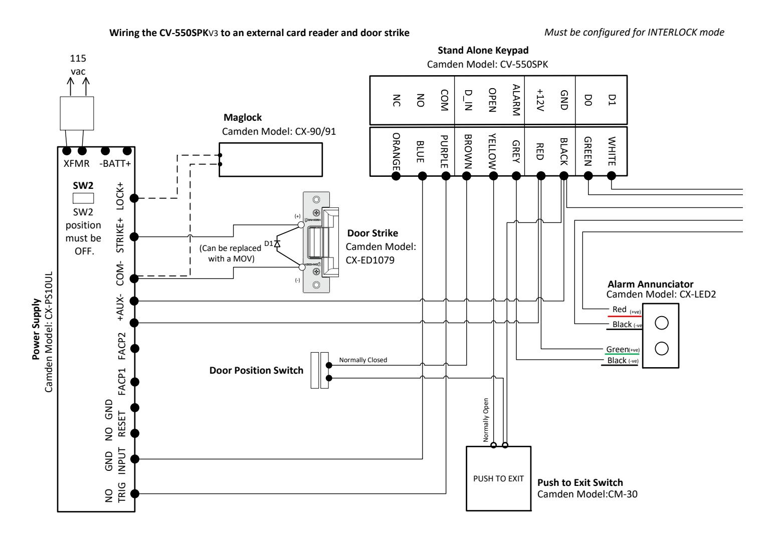
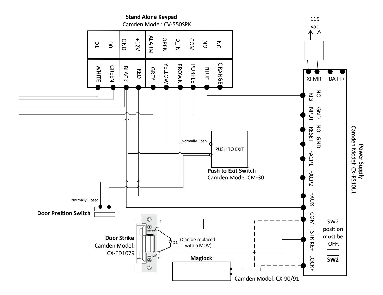
Wiring the CV‐550SPK V3 to an external card reader and door strike
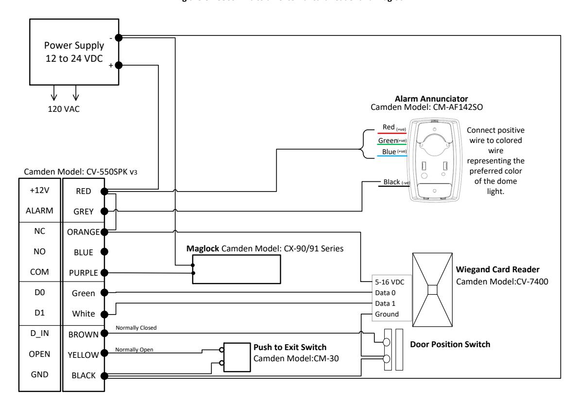
Wiring the CV‐550SPK V3 to an external card reader and maglock
INTERLOCK APPLICATION : Two keypads wired together
Wiring for DC Power (AC1 & GND) Wiring for AC Power (AC1 & AC2)
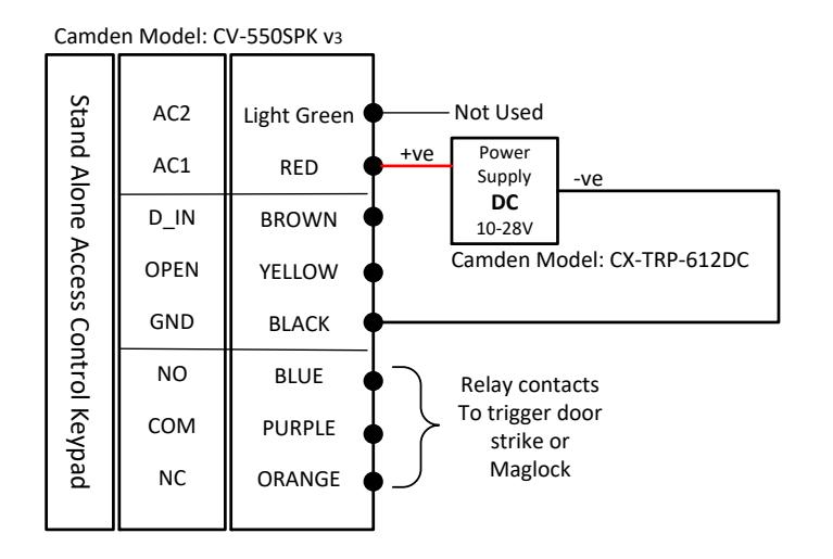
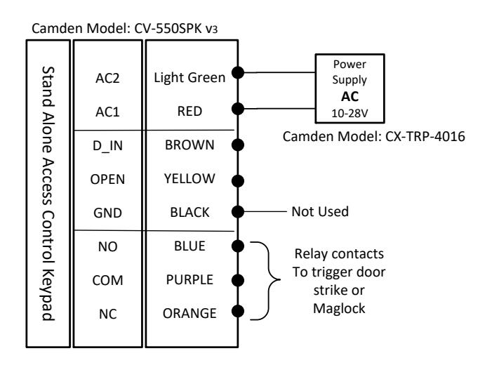
Note: Connect corresponding power as shown above to prevent damage to the keypad.
2.3 Commissioning the system
Once the keypad is powered, conduct the following test, Getting Started, until you can open the door by reading a card, input PIN or exit button.
3. GETTING STARTED
Writing Conventions:
- Keypad operation only can be used between these12 buttons; "0123456789*#"
- "…" means continue similar operation as indicated from previous operations.
- ","is not an actual operation, it's just punctuated.
- "()" means the series of numeric numbers which will be typed into the keypad, like a PIN code, ID number ,card number etc.
Operation Conventions:
- "Beep-"one long beep means the operation was correct. "beep-beep-beep" three short beeps mean operation was incorrect. LED light turn to green means operation was successful.
- "#" means previous operation was received by system, it normally used at the end of entering the digital numbers of PIN code, ID number, card number or parameter, when you type this key, it means input is finished.
- " * " means cancel current operation or back to previous menu
- Management menu is fixed to 2 digits, from 00~99, Don't press "#" on the keypad afterwards. After entering the 2 digits, the LED will turn to orange (or purple), if the operation failed you will hear "beep-beep-beep"3 short beeps.
- Under the management menu operation mode, if there is no activity detected without any operation over 30 seconds, it will revert to standby mode automatically.
Indicator light and buzzer prompt:
| Operation Status | Indicator light | Buzzer |
|---|---|---|
| Standby mode | Red | |
| Successful operation | Green | A long beep |
| Operation incorrect | 3 short beeps | |
| When admin card enter | 2 short beeps | |
| When admin card exit | A long beep | |
| Press digit key | A short beep | |
| Press * key | A long beep | |
| Inputting opening door PIN | Red slow flash | |
|
Both read card and input PIN Mode,
after reading the card |
Red slow flash | |
|
Multi-card reading open the door, when the card
reading is not over yet |
Red slow flash | |
| Enter the first zone admin main menu | Red slow flash | |
| Enter the first zone setting status | Orange | |
| The first unlock | Green | |
| Alarm | Red quick flash | Alarm Sound |
3.1 Enter management menu operation mode
* (Hold on for more than 2 seconds), (Input admin password) #
Note: Admin password is a 6 digits number, 888888 is the factory default admin password. The user must change the admin password when they use the keypad. A new admin password is required, otherwise the user cannot continue other operations. After inputting the new admin password, the LED light will flash green once and then back to red flash status, all of the other operations will be similar.
3.2 Change admin password
00, (New admin password) #, (Repeat new admin password) # Note: New admin password must be a 6 digit number.
3.3 Set controller to Single-door mode
Factory default setting is in single door mode. To confirm the mode, the user can set it again by following the steps: 03, 1#
3.4 Set door opening time to 2S
The factory default door opening time is 2 seconds. If user is not sure about the time period, set it again following steps: 34, 2 #
3.5 Add User Card
10, read card, read card …repeat the operation till the last user card.
Note: the keypad can read multiple card credentials continuously (Batch loading). When you hear a long "beep- "and the indicator light turns to green it means the new card was added successfully. After finishing enrolling the last card, press the * key to exit the add user card status.
3.6 Add User PIN
11(ID) #, (User PIN) #, (ID) #, (User PIN) #, …repeat the operation till the last user PIN.
Note: The user ID range is from 1 to 20,000 and must not be added before. User PIN is a 4~6 digits number and this number must not be 1234. Controller can add more users continuously, after the last user PIN, press the * key to exit the add User PIN status.
3.7 Exit Management menu operation mode
In Management menu operation mode, press * more than once until the indicator light turns to red and always bright which confirms you have exited the Management menu operation mode.
3.8 User open door
When the indicator light is red and always bright, read card, or (input user PIN) #, or press exit button.
Note: When the door opens, there is a long "beep" sound, and the indicator light turns to green when the door is unlocked.
4. BASIC FUNCTIONS
4.1 Management menu operations
In all modes, enter the first zone management menu, the management system settings and the first zone related settings' steps are:
key (Hold for more than 2 seconds), (Admin Password) # or to read zone 1 Set-card
Note: Admin Password is 6 digits, 888888 is the factory default admin password. User must change the Admin Password. A valid admin password is required otherwise the user cannot continue with other operations. If the Admin Password is correct, the indicator light will turn to green once and then back to red flash status. Other operations must be performed in this status.
If the user forgets the admin password or the user needs to use the management menu many times, they can read the first zone Set-card operation instead.
4.1.1 Change Admin Password
00, (New Admin Password) #, (Repeat Admin Password)#
Note: New Admin Password must be 6 digits
4.1.2 Set or delete Super-open-password
00,( 8 digits ) #, set Super-open-password 00,0000 #, delete Super-open-password
Note: these functions are available under the First zone management menu.
Super-open-password has the highest permission to open the door and it can use to open the door anytime .
4.1.3 Set admin card
01, 0#, read card, read card, …, Set 1-3 Set-cards.
01, 1#, read card, read card, …, Set 1-3 Add-cards.
01, 2#, read card, read card, …, Set 1-3 Delete-cards.
01, 3#, read card, read card, …, Set 1-3 Super-open-cards.
01, 4#, read card, read card, …, Set 1-3 Anti-duress-cards.
01, 5#, read card, read card, …, Set 1-3 Authorization-cards.
01, 6#, read card, read card, …, Set 1-3 Normal-open-cards.
Note: Each type of admin card can be divided several times to set till to 3pcs.
4.1.4 Delete admin card
- 02, 0000#, delete all 21 admin cards.
- 02, 0#, delete 3 Set-cards.
- 02, 1#, delete 3 Add-cards.
- 02, 2#, delete 3 Delete-cards.
- 02, 3#, delete 3 Super-open-cards.
- 02, 4#, delete 3 Anti-duress-cards.
- 02, 5#, delete 3 Authorization-cards.
- 02, 6#, delete 3 Normal-open-cards.
4.1.5 Set Keypad Mode
- 03, 0#, Set to Reader mode.
- 03, 1#, Set to Single-door mode.
- 03, 3#, Set to Interlock mode.
- 03, 9#, Set to Demo mode.
Note: Factory default mode are Single-door mode, menu effect will be different in different mode.
The valid menus for Reader mode are:00-04,09,40-42,50-57,60-64, among them, menu 01 and 02 can only add and delete admin password cards.
The valid menus for Single-door and interlock mode are: 00-04,09,10-12,20-22,30-36,40-45,50-57.
The valid menus for Demo mode are: 03,09,32,34,51-53,55.
4.1.6 Limits types of reading card
- 04, 0#, cannot read any card.
- 04, 1#, can read EM card only.
- 04, 2#, can read HID card only.
- 04, 4#, can read EM+HID card.
- 04, 7#, can read EM+HID+IC card.
Note: To read IC cards at 13.56MHz, a different model of keypad must be used.
4.1.7 Restore to default settings
09, 0000#
Note: After Restore to default settings, Admin Password is unchanged, Keypad mode is unchanged, admin cards and user card information are not deleted, and the specific default values are shown in the appendix.
4.1.8 Add User
4.1.8.1 Automatically generates ID numbers to add user card
Read card continuously to add user: 10, read card, read card, … {After finishing enrolling the last card, press the * key to exit the add user card status.}
Input 8-digit format card number to add user
10, 8# (8-digit format card number) #, 8# (8-digit format card number) #, …
Input 10-digit format card number to add user:
10,10# (10-digit format card number) #, 10# (10-digit format card number) #, …
Note: For example, card number is: 0004301875, 065,42035, front numbers are 10-digit format card number, the following numbers are 8-digit card number, 00 in front of number can be omitted, you can input 4301875 or 65,42035. The card number not separated by commas or other symbols is considered as 10-digit format card number. The following sections are dealt with according to this rule.
4.1.8.2 Specify ID number to add user card or PIN
Specify ID number and read card to add user:
11, (ID) #, read card, (ID) #, read card, …
Specify ID number and input 8-digit card number to add user:
11, (ID) # 8# (8-digit format card number) #, (ID) # 8# (8-digit format card number) #, …
Specify ID number and input 10-digit format card number to add user:
11, (ID) # 10# (10-digit format card number) #, (ID) # 10# (10-digit format card number) #, …
Specified ID number and input 4-6 digits PIN to add user:
11, (ID) # (User PIN) #, (ID) # (User PIN) #, …
Note: ID number are 1~5 digits between 1~20000, User PIN in zone 1 are any 4~6 digits, except 1234.
4.1.8.3 Specify first ID number to add serial number card users
Add 8-digit format serial number card users:
12, (ID) #, 8# (8-digit format card number) #, (card quantity) #
Add 10-digit format serial number card users:
12, (ID) #, 10# (10-digit format card number) #, (card quantity) #
Note: ID number are 1~5 digits, the range is1-20000, ID number plus card quantity must be less or equal to 20001. After add serial number cards, the first card will be based on ID number and card number, each time add one card, ID number and card number will add 1 at the same time till all cards are added. In order to prevent duplication of card numbers, please delete all user cards and admin cards before adding serial number cards.
4.1.9 Delete user
Delete all users:
20, 0000#
Delete user card by read card:
21, read card, read card, …
Delete user by input 8-digit format card number:
21, 8# (8-digit format number) #, 8# (8-digit format number) #, …
Delete user by input 10-digit format card number:
21, 10# (10-digit format number) #, 10# (10-digit format number) #, …
Delete user by input ID number
22, (ID) #, (ID number) #, …
4.1.10 Set open door methods
- 30, 0#, open door by card, you can open door by user card, but cannot open door by user PIN.
- 30, 1#, open door by card + PIN, read user card first, then input user PIN to open door.
- 30, 2#, default value, open door by cards or PIN, read user card or input user PIN to open door.
Note: Super-open-card or Super-open-password is not affected by any open door method; you can open door at any time.
4.1.11 Set Multi-card to open door
- 31, 1#, default value, read 1 card to open door.
- 31, (2-10)#, read 2~10 cards in turn to open door(The open door method must set to: open door by card).
4.1.12 Set lock working mode
- 32, 0#, default value, set lock to Delay mode. After an unlock operation, the lock is opened , then the lock will be closed automatically after a few moment of delay. Apply to normal open.
- 32, 1#, set lock to Switch mode. After an unlock operation, the lock will latch open until another unlock operation again, the lock will lock, and so on.
- 32, 2#, set lock to Normal-open mode. Under this mode, the lock will latch open, not controlled by other unlocking action. If the user doesn't want to use the Normal-open mode, the administrator will need to change the mode to the other two modes.
Note: A better way to implement the Normal-open mode is using a Normal-open card in the first mode, it can switch to Normal-open mode and normal status quickly. For the programming of Normal-open card, see the relevant chapter of admin cards and their operation.
4.1.13 Set Limits User Mode
- 33, 0#, disable users to use.
- 33, 1#, default value, enable users to use.
Notes: A better way to implement the limits of user mode is operation by Authorization-card, it can switch to disable and enable users to operate quickly. The operation of Authorization-card, see relevant chapter of admin cards operation.
4.1.14 Set Open-time
- 34, 0#, set Open-time to 50mS, apply to electrically controlled lock for external instantaneous large current
- 34, (1-999) #, the default value is 2, set Open-time from 1 to 999S.
4.1.15 Door Ajar Alarm Period
-
35, (0-99) #, the default value is 10, set the time that notifies when the user has not closed the door after opening it. When the door is left open more than (how many) seconds the buzzer will begin to beep for notification.
- 36, (0-99) #, the default value is 10, set the duration limit for beeping.
Note: If you don't need notification, can set the time for warning to 0.
4.1.16 Set Alarm-time
- 40, 0#, default value, if set Alarm-time to 0 means no alarm.
- 40, (0-99) #, Alarm-time is set from 1 to 99 minutes.
4.1.17 Set tampering alarm function
- 41, 0#, default value, disable tampering alarm function.
- 41, 1#, enable Anti-dismantle alarm function.
Note: When the Keypad is dismantled, an alarm signal will be send out at the same time. The alarm can be canceled by inputting an Admin Password, reading an admin card or user card.
4.1.18 Set alarm or doorbell output function
- 42, 0#, default value, alarm wire output alarm signal voltage.
- 42, 1#, alarm wire output doorbell signal voltage.
Note: The Alarm wire is internally connected with the drain of the NMOS transistor, and the output is active low, which can drive the current less than 1A.
4.1.19 Set Error lockout function
- 43, 0#, default value, normal working mode.
- 43,1#, alarm working mode, when error operation times exeeds the allowed times, the Keypad alarm will beep and it send out an alarm signal.
-
43, 2#, locked working mode, when error operation times exeeds the allowed times, the Keypad will lock up for some time. User cannot press any key or read card during that time.
- 44, (1-10)#, default value is 10, set maximum attempts from 1 to 10 .
- 45, (1-99)#, default value is 10,set locked out time after the PIN or card attempts exceed the maximum times, from 1 to 99 minutes.
Note: Lock out function prevents and unlimited PIN number or unauthorized cards to open the door in a short period of time, the default period is within 10 minutes of invalid PIN or invalid card number reads exceeds the default setting, the controller will alarm or lock up for some time.
4.1.20 Set LED indicator light mode
- 50, 0#, standby, LED indicator light is off.
- 50, 1#, default value, standby, LED indicator light always red.
- 50, 2#, standby, LED turns green in reader mode, LED turns red in other modes.
4.1.21 Adjust the brightness of the red indicator
- 51, 1, 1, ... ,decrease brightness
- 51, 2, 2, ..., increase brightness
Note: The brightness of the indicator light can be adjusted 21 different levels. Each time you press the "1" key, it decrease 1 level of brightness. Press and hold on the "1" key, the brightness will continuously decrease. When it reaches to minimum level of brightness, the keypad will beep twice. Each time you press the "2" key, the red LED will increase the level of brightness. Press and hold on the "2" key, the brightness will continuously increase. When it reaches to the maximum brightness the controller will beep twice.
4.1.22 Set key backlit mode
- 52, 0#, Normal-off mode for key backlit.
- 52, 1#, default value, Normal-on mode for key backlit.
- 52, (2-99) #, Automatic mode for key backlit, the keypad will revert to micro lighting over 2 to 99 seconds.
4.1.23 Adjust brightness of key backlit
- 53, 1, 1, ... , decrease brightness
- 53, 2, 2, ... , increase brightness
Note: The brightness of the key backlight can be adjusted to 21 levels. Each time you press the 1 key, the keypad back lighting decreases 1 level of brightness, pressing and holding the 1 key automatically decrease the brightness, when it has been adjusted to a minimum brightness, the keypad "beep" two times, each time you press the 2 key, increase 1 level of brightness, press and hold the 2 key shall automatically increase the brightness, when it has been adjusted to the maximum brightness it will "beep" two times.
4.1.24 Set buzzer mode
- 54, 0#, disable buzzer.
- 54, 1#, default value, enable buzzer.
Note: Enable or disable buzzer is only for normal user operation, such as the sound of opening door by PINs or read cards. When you press the * key for 2 seconds, the buzzer is forced to enable, such as entering the management menu or change the user PIN state. In addition, the alarm tone is not controlled by this setting, and the buzzer can still send an alarm tone when the buzzer disabled.
4.1.25 Adjust key volume
- 55, 1, 1, ... , decrease volume.
- 55, 2, 2, ... , increase volume.
Note: The key volume can be adjusted to 15 levels. Each time you press the 1 key, decreases 1 level of volume, pressing and holding the 1 key shall automatically decrease the volume, when it has been adjusted to a minimum volume, it will "beep" two times, each time you press the 2 key, increase 1 level of volume, press and hold the 2 key shall automatically increase the volume, when it has been adjusted to the maximum volume, it will "beep" two times.
4.1.26 Set the # key be used as a doorbell key
- 56 0#, default value, the # key can't be used as doorbell key.
- 56, 1#, the # key can be used as doorbell key
Note: When the # key is used as doorbell key, if the # key must be the first key, then it is doorbell, If the # key is pressed after the digital key, then it is a confirmation function.
4.1.27 Set doorbell key mode
- 0#, default value, the doorbell key is invalid.
- 57, 1#, the doorbell key is valid, but without volume.
- 57, 2#, the doorbell key is valid, with "ding dong" tone
Note: If the alarm wire is set to door bell function [Refer to 4.1.18], pressing the # key shall provide positive voltage to the gray wire with a limit of less than 1 Amp.
4.1.28 Set reader output format
4.1.28.1 Set facility code
60, (0-255)#, default value is 0, set facility code.
Note: When the key output format is a multi key buffer output, the facility code will be used, See the following sections for specific selections
4.1.28.2 Set D0 & D1 output format
- 61, 0#, D0 & D1 output wiegand format.
- 61, 1#, D0 output RS232-TTL-HEX format.
- 61, 2#, D0 output RS232-TTL-ASCII-8 format
- 61, 3#, D0 output RS232-TTL-ASCII-10 format.
Note: The wiegand format is an international protocol for access control products. But the width of pulse and interval time are different. Our standard: Pulse's high level is 5V and low level is 0V. Width is 40uS, interval time is 2mS.
RS232-TTL-HEX format refers to the standard RS232 communication protocol data output, TTL level 0-5V, the output data is output by the card byte HEX format.
The output RS232-TTL-ASCII-8 format is the output data is ASCII character format, card number data is 8 bit format, and same as the ordinary EM card marked on the 8 bit card number, but omit the 0 in front of it.
The output RS232-TTL-ASCII-10 format is the output data is ASCII character format, card number data is 10 bit format, and same as the ordinary EM card marked on the 10 bit card number, but omit the 0 in front of it.
For example, a 3 byte number of RS232-TTL-HEX format is A83EF6, the actual output is A83EF6, the RS232-TTL-ASCII-8 format is 168,16118, the actual output is 16816118, the RS232-TTL-ASCII-10 format is 0011026166, the actual output is 11026166.
4.1.28.3 Set wiegand output format for reading card
62, (26-66)#, default value is 26, the Wiegand output format for reading card can be set from 26-66.
4.1.28.4 Set wiegand output parity format for reading card
- 63, 0# wiegand output without parity check.
- 63, 1# default value, wiegand output with parity check (EO format)
Note: EO format is standard wiegand format. Even check data add in front and Odd check data add in the end.
4.1.28.5 Set wiegand output format for pressing key
- 64, 0#, default value, single key output, 4 bits wiegand data(no check bit).
- 64, 1#, single key output, 6 bits wiegand data( with parity bit).
- 64, 2#, single key output, 8bits wiegand data(with complement check bit).
- 64, 3#, 4 digit key buffered output, facility code + binary PIN, wiegand 26-66 bit.
- 64. 4#, 1-5 digit key + # key buffered output, facility code + binary PIN, wiegand 26-66 bit.
- 64. 5#, 6 digit key buffered output, BCD code, wiegand 26-66 bit.
Note: The keys are output in the form of Wiegand signals, and the keys correspond to the outputs as follows:
Single key output, 4 bits wiegand data (no check bit). Every key output a 4 bit data, Corresponding relation is:
| 1(0001), | 2(0010), | 3(0011) |
|---|---|---|
| 4(0100), | 5(0101), | 6(0110) |
| 7(0111), | 8(1000), | 9(1001) |
| *(1010), | 0(0000), | #(1011) |
Single key output, 6 bits wiegand data ( with parity bit). Every key output a 6 bit data, Corresponding relation is:
| 1(000010), | 2(000100), | 3(000111) |
|---|---|---|
| 4(101001), | 5(101010), | 6(101100) |
| 7(101111), | 8(110001), | 9(110010) |
| *(110100), | 0(000001), | #(110111) |
Single key output, 8bits wiegand data (with complement check bit). Every key output a 8 bit data, Corresponding relation is:
| 1(11100001), | 2(11010010), | 3(11000011) |
|---|---|---|
| 4(10110100), | 5(10100101), | 6(10010110) |
| 7(10000111), | 8(01111000), | 9(01101001) |
| *(01011010), | 0(11110000), | #(01001011) |
4 digit key buffered output, facility code + binary PIN, wiegand 26-66 bit. Press any 4 digits, output a wiegand 26-66 card number. If facility code is 255, press 1234, then the output binary PIN will be:
0 11111111 0000010011010010 0.
1-5 digit key + # key buffered output, facility code + binary PIN, wiegand 26-66 bit. P ress any 1-5 digits less than 65535,then press #, if facility code is 255, press 65535#, then the output binary number will be:
0 11111111 1111111111111111 1.
6 digit key buffered output, BCD code, wiegand 26-66 bit . Press any 6 digits, if press 123456, then the output binary number will be: 0 0001 0010 0011 0100 0101 0110 0.
4.2 Admin card or PIN operation
Admin card is divided into zone 1 and zone 2 {only for 2 door keypads}, admin card in different zone operate in different zone, the following description
Use admin card operation in the zone 1. admin card operation in the zone 2 will be the same.
4.2.1 Set-card operation
The main function of Set-card is to replace the input Admin Password into the management menu operation. It is suitable for users who repetitively forget the Admin Password or frequently require to enter the management menu operation. Its operation is:
Read Set-card, equivalent to operation: * ( Hold down for more than 2 seconds), (Admin password) #.
Note: After reading Set-card, the indicator lights are red flashing, indicating that the management menu operation mode has been entered and other operations can be performed.
4.2.2 Add-card operation
Read Add-card, read user card, read user card, read Add-card.
Note: Add-card is mainly used for a quick and easy method to add the user card. First read Add-card, sound "beep" two short sound, light is orange, indicating the keypad has entered the add user card state, second read Add-card, sound "beep" a long sound, light turns red, indicate exiting add user card state.
4.2.3 Delete-card operation
Read Delete-card, read user card, read user card, read Delete-card.
Note: Delete-card is mainly used for a quick and easy method to delete the user card, first read Delete-card, sound "beep" two short sound, light is orange, indicate entering the delete user card state, second read Delete-card, sound "beep" a long sound, light turns red, indicate exiting delete user card state.
4.2.4 Super-open-card operation
Read Super-open-card.
Note: Super-open-card has the highest open priority to all other opening methods. The Super-open-card will open the door.
4.2.5 Super-open-password operation
(8 digit Super-open-password) #.
Note: Super-open-password is 8 digits. The Super-open-password must be different in two zones or it can only open the door in Zone 1. Super-open-password has the highest open priority of all methods to open the door. The super-open password will open the door.
4.2.6 Anti-duress-card operation
Read Anti-duress-card.
Note: Anti-duress-card has the same authority as the Super-open-password. The only difference is after reading the Antiduress-card, the door will open while triggering the alarm signal.
4.2.7 Authorization-card operation
Read Authorization-card once, two short beeps, limit users.
Read Authorization-card again, one long beep, release limit.
Note: Authorization-card is also called header card, it authorizes users. By default, users can operate properly, you can use an Authorization-card when you need to restrict user access.
4.2.8 Normal-open-card operation
Read Normal-open-card once, two short beeps, lock keep open, not controlled by other unlocking action.
Read Normal-open-card again, one long beep, release normal open state.
4.3 Users operation
4.3.1 Get user card or PIN
Users must obtain the user card or user PIN from the administrator for the first time. The user PIN can be obtained separately from the administrator and can also be changed by the user card. The number of user PIN digits are restricted to 4-6 digits.
4.3.2 Change user PIN
Change user PIN by card:
* (Hold down for more than 2 seconds), read card, (Old PIN)#, (New PIN)#, (Repeat new PIN)#
Note: Every card's default PIN is 1234 which can't be use to open door unless you change it.
Change user PIN by ID number:
*( Hold down for more than 2 seconds), (ID number), (Old PIN)#, (New PIN)#, (Repeat new PIN)#
Note: You need to know ID when you change PIN through this method. ID number needs to be obtained from the administrator. The old PIN cannot be the initial PIN 1234.
4.3.3 User Open door
Open door by Single card:
read user card
Open door by multi-card:
Read user card, read user card, ...
Open door by User card or PIN:
Read user card or (User PIN)#
Open door by User card and PIN:
Read user card, (User PIN)#
Exit operation:
Press exit button
Note: In reference to the exit operation, make sure that the Keypad is not in a disabled user state. Opening the door by multi-card requires a set of good quantity of cards. If card or PIN is valid, the user will hear a long "beep", the lock will be opened. During the opening time, LED turns green. After that, LED turns red. In card & PIN open mode or multi-card open door mode, the interval time of reading card or inputting PIN cannot be more than 5 seconds.
4.4 Other operations
4.4.1 Cancel alarming
Read admin or the user card, or (Admin Password) #,
4.4.2 Admin Password initialization
When you forget the Admin Password, you can restore it to the initial password by special operation. Operation as follows: Power off, press and hold the # key, and power on. Release the # key after two "beep". Admin password will be restored to 888888. But the other parameters, the info of the card and pin will be kept the same.
4.4.3 Restore factory settings
When you forget the Admin Password, or when the user changed any of the various parameters, you can return to the orignal status by restoring the factory default settings, as follows:
Power off, and hold the * Key, and power on. Release the * key after two "beep". Admin Password will be restored to 888888, while the Keypad parameters will revert to factory default settings, the specific default values shown in the schedule, other cards and PIN information will not be deleted.
4.5 Operation characteristics in different Keypad modes
4.5.1 Operation characteristics in reader mode
In the reader mode, you can only operate menus: 00-04, 09, 40-42, 50-57, 60-64. Among them, the 01 and 02 menus can only be adding and deleting Set-card.
Reading Set-card, the Keypad does not output a Wiegand signal, reading the other card or inputting user PIN, the Keypad will output a Wiegand signal.
The three control wires, LED_R, LED_G and BEEP, their functions are as follows:
LED_G: Green LED control wire, LED turns to green when low level.
LED_R: Red LED control wire, LED turns to red when low level.
BEEP: Buzzer control wire, Buzzer sounds when low level.
When LED_G & LED_R turns to low level together, the LED indicator light will turn to orange (LED indicator light mode is 0),Green(LED indicator light mode is 1) or red ( LED indicator light mode is 2) .
4.5.2 Operation characteristics in Single-door mode
The default mode is Single-door mode, most applications work in this mode, in this mode, you cannot operate the menu 60-64.
4.5.3 Operation characteristics in Interlock mode
Interlock mode is referring to interlocking between two doors, install a Keypad and a Magnetic Door Contact on each door, and then set keypad to Interlocked mode. One door can be opened only when the two doors are closed. If a door has been opened but not closed, another door cannot be opened. The other operations of the interlock mode are the same as that of the Singledoor mode.
4.5.4 Operation characteristics in Demo mode
Demo mode is a mode for Single-door mode, primarily for display purposes or without security, as a tool to use any card to open the door. In this mode, any card or 6-digit PIN can open a door without authorization. When entering management mode, only menus 03, 09, 32, 34, 51-53 and 55 are valid.
5. MANAGEMENT MENU SUMMARY TABLE
5.1 Reader mode management menu summary table
| Way to enter menu : * (Hold down for more than 2 seconds), (Admin password) # | |||||
|---|---|---|---|---|---|
| Menu | Parameter or operation step | Function | Default value | ||
| 00 |
(New admin password) #,
(Repeat new admin password) |
Change admin password | 888888 | ||
| 01 | 0#, read card, read card, … | Set 1-3 Set-cards | |||
| 02 | 0# | Delete 3 Set-cards | |||
| Way to enter menu : * (Hold down for more than 2 seconds), (Admin password) # | ||||
|---|---|---|---|---|
| Menu | Parameter or operation step | Function | Default value | |
| 0# | Reader mode | |||
| 1# | Single-door mode | |||
| 03 | 3# | Interlock mode | 1 | |
| 9# | Demo mode | |||
| 1# | Only read EM card | |||
| 2# | Only read HID card | |||
| 04 | 4# | Read EM and HID card | 7 | |
| 7# | Read EM, HID and IC card | |||
| Restore default settings, admin password | ||||
| 09 | 0000# | and user information unchanged | ||
| 0, # | Set Alarm time to 0, means no alarm | |||
| 40 | (1-99)# | Set the alarm time to 1-99 minutes | 0 | |
| 0# | Disable Anti-dismantle alarm | |||
| 41 | 1# | Enable Anti-dismantle alarm | 0 | |
| 0# | Alarm lead output alarm signal voltage | |||
| 42 | 1# | Alarm lead output doorbell signal voltage | 0 | |
| 0# | Indicator light is always off | |||
| 1# | Red indicator light is always on | |||
| 50 | Green indicator light is always on(reader | 1 | ||
| 2# | mode) | |||
| Decrease the brightness of the normally | ||||
| 1,1,…,# | bright red indicator | 18 | ||
| 51 | Increase the brightness of the normally bright | |||
| 2,2,…,# | red indicator | |||
| 0# | Key backlit is always off | |||
| 1# | Key backlit is always on | |||
| 52 | After delay 2-99 seconds, Key backlit turn to | 1 | ||
| (2-99)# | micro light | |||
| 1,1,…,# | Decrease the brightness of the backlit | |||
| 53 | 2,2,…,# | Increase the brightness of the backlit | 14 | |
| 0# | Disable the buzzer | |||
| 54 | 1# | Enable the buzzer | 1 | |
| 1,1,…,# | Decrease the keypad tone | |||
| 55 | 2,2,…,# | Increase the keypad tone | 10 | |
| 0# | The # key can't be used as doorbell key | |||
| 56 | 1# | The # key can be used as doorbell key | 0 | |
| Way to enter menu : * (Hold down for more than 2 seconds), (Admin password) # | ||||
|---|---|---|---|---|
| Menu | Parameter or operation step | Function |
Default
value |
|
| 0# | The doorbell key is invalid. | |||
| 1# | The doorbell key is valid, but without volume. | |||
| 57 | 2# |
The doorbell key is valid, with "ding dong"
tone. |
0 | |
| 60 | (0-255)# | Set facility code | 0 | |
| 0# | D0&D1 output wiegand format. | |||
| 1# | D0 output RS232-TTL-HEX format. | |||
| 61 | 2# | D0 output RS232-TTL-ASCII-8 format. | 0 | |
| 3# | D0 output RS232-TTL-ASCII-10 format. | |||
| The wiegand output format for reading card | ||||
| 62 |
(26-66)#
can be set from 26-66 bits. |
26 | ||
| 0# | Wiegand output without parity check. | |||
| 63 | 1# | wiegand output with parity check(EO format). | 1 | |
| 0# | Single key output, 4 bits wiegand data(no check bit). | |||
| Single key output, 6 bits wiegand data( with | ||||
| 1# | parity bit). | |||
| Single key output, 8bits wiegand data(with | 0 | |||
| 2# | complement check bit). | |||
| 64 | 3# | 4 digit key buffered output | ||
| 4# | 1-5 digit key + # key buffered output | |||
| 5# | 6 digit key buffered output | |||
5.2 Single-door mode management menu summary table
| Way to enter menu : * (Hold down for more than 2 seconds), (Admin password) # | |||
|---|---|---|---|
| Menu | Parameter or operation step | Function |
Default
value |
| (New Admin Password) #, (Repeat new Admin | |||
| Password) | Change admin password | 888888 | |
| 00 | (8 digits )# | Set Super-open-password | |
| 0000# | Delete Super-open-password | ||
| 0#, read card, read card, … | Set 1-3 Set-cards. | ||
| 1#, read card, read card, … | Set 1-3 Add-cards. | ||
| 2#, read card, read card, … | Set 1-3 Delete-cards. | ||
| 3#, read card, read card, … | Set 1-3 Super-open-cards. | ||
| 4#, read card, read card, … | Set 1-3 Anti-duress-cards. | ||
| 01 | 5#, read card, read card, … | Set 1-3 Authorization-cards. | |
| 6#, read card, read card, … | Set 1-3 Normal-open-cards. | ||
| 0000, # | Delete 21 admin cards | ||
| 02 | 0# | Delete 3 Set-cards. | |
| Menu | Parameter or operation step | Function | Default value |
|---|---|---|---|
| 1# | Delete 3 Add-cards. | ||
| 2# | Delete 3 Delete-cards. | ||
| 3# | Delete 3 Super-open-cards. | ||
| 4# | Delete 3 Anti-duress-cards. | ||
| 5# | Delete 3 Authorization-cards. | ||
| 6# | Delete 3 Normal-open-cards. | ||
| 0# | Reader mode | ||
| 1# | Single-door mode | ||
| 3# | Interlocked mode | ||
| 9# | Demo mode | 1 | |
| 03 | 1# | Only read EM card | |
| 2# | Only read HID card | ||
| 4# | Read EM and HID card | ||
| Restore default settings, admin password | |||
| 09 | 0000# | and user information unchanged. | |
| Read card, read card, … | Read card continuously to add users. | ||
| 8#(8-digit format card number)#,8#(8-digit for | Input 8-digit format card number to add | ||
| mat card number)#, … | users. | ||
| 10 | 10#(10-digit format card number)#,10#(10-digit | Input 10-digit format card number to | |
| format card number)#, … | add users. | ||
| (ID)#, read card, (ID)#, read card, … |
Specify ID number and read card to add
user. |
||
|
(ID)#8#(8-digit format card number)#,
ID)#8#(8-digit format card number)#, … |
Specify ID number and input 8-digit
card number to add user. |
||
| 11 |
(ID)#10#(10-digit format card number)#,
(ID)#10#(10-digit format card number)#, … |
Specify ID number and input 10-digit for
mat card number to add user. |
|
| (ID)#(user PIN)#, (ID)#(user PIN)#, … |
Specified ID number and input 4-6 digits
PIN to add user. |
||
|
(ID)#, 8#(8-digit format card number)#,
(card quantity)# |
Add 8-digit format serial number card users. | ||
| 12 |
(ID)#, 10#(10-digit format card number)#,
(card quantity)# |
Add 10-digit format serial number card users | |
| 20 | 0000# | Delete all users. | |
| Read card, read card, … | Delete card user by reading card | ||
|
8#(8-digit format number)#, 8#(8-digit for
mat number)#, … |
Specified ID number and input 8-digit for
mat card number to delete user. |
||
| 21 |
10#(10-digit format number)#,
10#(10-digit format number)#, … |
Specified ID number and input 10-digit for
mat card number to delete user. |
|
| 22 | (ID)#, (ID)#, … | Input ID number to delete user. |
| Way to enter menu : * (Hold down for more than 2 seconds), (Admin password) # | |||
|---|---|---|---|
| Menu | Parameter or operation step | Function | Default value |
| 0# | Open door way by card | ||
| 1# | Open door way by card and PIN | 2 | |
| 30 | 2# | Open door way by card or PIN | |
| 1# | Set one card to open door | ||
| 31 | (1-10)# | Set 2-10 cards together to open door | 1 |
| 0# | Set lock to Delay mode | ||
| 1# | Set lock to Switch mode | 0 | |
| 32 | 2# | Set the lock to Normal-open mode | |
| 0# | Disable users to use. | ||
| 33 | 1# | Enable users to use. | 1 |
| 0# | Set Open-time to 50mS | ||
| 34 | (1-999)# | Set Open-time from 1 to 999S | 2 |
| After opening the door, delay 0-99 seconds to | |||
| 35 | (0-99)# | start the tone | 10 |
| 36 | (0-99)# | Set the closing prompt tone for 0-99 seconds. | 10 |
| 0,# | Set the alarm time to 0, means no alarm | ||
| 40 | (1-99)# | Set the alarm time to 1-99 minutes | 0 |
| 0# | Disable anti-dismantle alarm function. | ||
| 41 | 1# | Enable anti-dismantle alarm function. | 0 |
| 0# | Alarm lead output alarm signal voltage | ||
| 42 | 1# | Alarm lead output doorbell signal voltage | 0 |
| 0# | Normal operate mode | ||
| 1# | Enable lock out alarm function | ||
| 43 | 2# | Enable lock out locked function | 0 |
| 44 | (1-10)# | Set lock out wrong attempts 1-10 | 10 |
| 45 | (1-99)# | Set lock out locked time 1-99 minutes | 10 |
| 0# | Indicator light is always off | ||
| 1# | Red indicator light is always on | ||
| 50 | Green indicator light is always on (reader | 1 | |
| 2# | mode) | ||
| Decrease the brightness of the normally | |||
| 1,1,…,# | bright red indicator | ||
| 51 | Increase the brightness of the normally bright | 18 | |
| 2,2,…,# | red indicator | ||
| 0# | Key backlit is always off | ||
| 1# | Key backlit is always on | ||
| 52 | After delay 2-99 seconds, Key backlit turn to | 1 | |
| (2-99)# | micro light | ||
| 1,1,…,# | Decrease the brightness of the backlit | ||
| 53 | 2,2,…,# | Increase the brightness of the backlit | 14 |
| 54 | 0# | Disable the buzzer | 1 |
CV-550 SPK V3 REFERENCE MANUAL
INSTALLATION INSTRUCTIONS
| Way to enter menu : * (Hold down for more than 2 seconds), (Admin password) # | |||
|---|---|---|---|
| Menu | Parameter or operation step | Function | Default value |
| 1# | Enable the buzzer | ||
| 1,1,…,# | Decrease the keypad tone | ||
| 55 | 2,2,…,# | Increase the keypad tone | 10 |
| 0# | The # key can't be used as doorbell key | ||
| 56 | 1# | The # key can be used as doorbell key | 0 |
| 0# | The doorbell key is invalid. | ||
| 1# | Doorbell button valid, no keypad sound | 0 | |
| 57 | 2# | Doorbell button valid & sound Dingdong | |
5.3 Interlock mode management menu summary table
Please refer to" single-door mode management menu summary table".
5.4 Demo mode management menu summary table
| Way to enter menu : * (Hold down for more than 2 seconds), (Admin password) # | |||
|---|---|---|---|
|
Menu
Parameter or operation step Function |
Default value | ||
| 0# | Reader mode | ||
| 03 | 1# | Single-door mode | 1 |
| Way to enter menu : * (Hold down for more than 2 seconds), (Admin password) # | ||||
|---|---|---|---|---|
| Menu | Parameter or operation step | Function | Default value | |
| 3# | Interlock mode | |||
| 9# | Demo mode | |||
| Restore default settings, admin password and user | ||||
| 09 | 0000# | information unchanged. | ||
| 0# | Set lock to Delay mode | |||
| 1# | Set lock to Switch mode | 0 | ||
| 32 | 2# | Set the lock to Normal-open mode | ||
| 0# | Set Open-time to 50mS | 2 | ||
| 34 | (1-999)# | Set Open-time from 1 to 999S | ||
| 1,1,…,# | Decrease the brightness of the normally bright red indicator | 18 | ||
| 51 | 2,2,…,# | Increase the brightness of the normally bright red indicator | ||
| 0# | Key backlit is always off | |||
| 1# | Key backlit is always on | 1 | ||
| 52 | (2-99)# | After delay 2-99 seconds, Key backlit turn to micro light | ||
| 1,1,…,# | Decrease the brightness of the backlit | |||
| 53 | 2,2,…,# | Increase the brightness of the backlit | 14 | |
| 1,1,…,# | Decrease the keypad tone | |||
| 55 | 2,2,…,# | Increase the keypad tone | 10 | |
6. PRECAUTIONS IN USE
- Wiring must not be connected wrong, especially the power line, otherwise the Keypad may get permanently damaged and not work properly.
- Because the keypad internal relay is used for signal output, it cannot directly drive large power loads. To ensure the longterm stable operation of the keypad, electric locks should not be connected directly with NO, NC, COM of the keypad, but be driven by an access control power supply or through an isolation relay module (CX-IRB).
- When you enter the management mode or change the user PIN, you must press and hold the * key for more than two seconds to be valid.
- To encourage security, the default admin initial password 888888 only supports the menu 00, which encourages users to change the 6-digit admin password, or they cannot access other settings.
- The factory default mode is the single-door mode. If you need another mode function, you must enter the appropriate mode to have the keypad function for your application. In different modes, the management menu is also different.
7. COMMON TROUBLESHOOTING
| Fault phenomenon | Possible causes | Troubleshooting | |
|---|---|---|---|
|
1. The gauge of power wires are too thin,
resulting in the voltage being too low. |
Replace wires with higher gauge wires ≥
AWG #18. |
||
|
Indicator light is not working
properly |
2. Wiring connection is incorrect, or power
wires are not powered. |
Wiring in the correct way. | |
| 3. Set the indicator light normal off | Set to normal mode. | ||
|
1. Hold the * key in front of the password
longer than 2 seconds. |
Operate in the right way | ||
| Fail to enter management mode. | 2. Input wrong admin password. | Enter the correct password | |
| 3. Forget admin password. |
Change by Setting card or press the #
key to initialize. |
||
|
Can enter management mode, but
part of the menu is invalid. |
1.can't setting some menu in default
password, only can change admin password. |
Change Admin password. | |
|
2. The Keypad mode is incorrect, and some of
the menus are blocked. |
Set to right Keypad mode | ||
|
1. Keypad will beep three times if it is not the
valid user card. |
Add the user card again | ||
| User card can't open the door |
2. Keypad will beep three times if the user is
disable. |
Enable user. | |
|
3. One beep indicates keypad relay tripped
and wiring should be checked. |
Make sure the connection is correct. | ||
|
1. The power supply voltage at the keypad is
low. |
Change to linear power supply or connect
the housing to the ground. |
||
|
Reading card distance is too
close. |
2. Part of the electrical lock interference is
too large. |
Choose the qualified lock or parallel
connect a 470uF/25V electrolytic capacitor at the two ends of the lock |
|
8. COMPATIBLE PERIPHERALS
Camden supports CV-550 access control system with an extensive line of readers, credentials and system peripherals.
| Card Readers - Proximity | |||
|---|---|---|---|
| CV-7400 | Narrow mullion mount | ||
| CV-7820 | Single gang mount | ||
| Credentials | |||
| CV-CSH | HID format clam shell style card, package of 10 | ||
| CV-CSH-B | HID format clam shell style card, bulk package of 100 | ||
| CV-ISH | HID format, ISO prox card, package of 10 pieces | ||
| CV-ISH-B | HID format, ISO prox card, bulk package of 100 pieces | ||
| CV-KTH | HID format, proximity key tag, package of 25 pieces | ||
| CV-CSE | EM format, ISO card, package of 10 pieces | ||
| CV-CSE-B | EM format, ISO card, bulk page of 100 pieces | ||
| CV-KTE | EM format, key tag, package of 25 pieces | ||
| CM-RQE70A | PIR Request to Exit detector, c/w 2 form C contacts, 12/24 VDC | ||
| CM-RQE70ABK | PIR Request to Exit detector, black, c/w 2 form C contacts, 12/24 VDC | ||
| CM-RQEPW | PIR single gang adaptor plate, white | ||
| CM-RQEPK | PIR single gang adaptor plate, black | ||
| CM-30C |
Universal LED illuminated (red and green): 'Push to Exit', 'Exit', 'Occupied When Lit', (13) English and
French insert labels, 12V - 28V bilingual versions and wheelchair symbol. |
||
| CM-30U |
Universal (13) English and Spanish insert labels, 12V - 28V LED Illuminated (red and green): 'Push to Exit',
'Exit', 'Occupied When Lit' and wheelchair symbol. |
||
| CM-30E |
English 'Push to Exit', 12-28V LED Illuminated. For French language 'Poussez Pour Ouvrir', order
CM-30F. Green, 'Push to Exit' |
||
| CM-330 | Battery Powered, Wireless Touchless Switch, w/ built-in Lazerpoint RF(tm) wireless transmitter. | ||
| CM-AF500 |
Single gang LED Illuminated annunicator labels include: 'Occupied When Lit', 'Locked When Lit'
(Green), 'Occupied/Occupe' (Red), 'Armed' (Red), 'Unlocked' (Green) |
||
| CM-AF501SO |
Single gang LED annunciator with adjustable sounder 'ASSISTANCE REQUESTED'. Add suffix 'F' for
French, suffix 'FE' for bilingual |
||
| CX-TRP-612DC | Plug-in 12 VDC Power Supply | ||
|
User
ID# |
Card # (8 or 10 digit) |
User PIN#
(4 to 6 digit) |
Name | Suite/Office/Ref |
|---|---|---|---|---|
| 1 | ||||
| 2 | ||||
| 3 | ||||
| 4 | ||||
| 5 | ||||
| 6 | ||||
| 7 | ||||
| 8 | ||||
| 9 | ||||
| 10 | ||||
| 2000 |