CV-550SPK V3 Manual English
Open the original PDF document
View PDF

Door Activation Devices
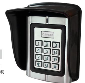
CV-550SPK V3 Waterproof Keypad/Reader/Controller
INSTALLATION INSTRUCTIONS
THIS PACKAGE INCLUDES:
(1) Keypad CV-550SPK V3 (4) Wall plugs
(1) User Manual (6 x 27 mm, used for mounting)
(4) Self tapping screws
(1) Screw driver (3.5 x 27 mm, used for mounting)
(2) 6-32x1" Pan head machine screws to mount to single gang switch box.
1. DESCRIPTION
The CV-550SPK V3 is a back-lit single door multifunction standalone access control keypad with a Wiegand input/output interface. It is suitable for mounting either indoors or outdoors in harsh environments. It is housed in a strong, sturdy and vandal proof Zinc Alloy electroplated case. The supplied shield will provide greater visibility of the illuminated status LED'S as well as keeping weather elements off of the face of the keypad. The electronics are fully potted so the CV-550SPK V3 is waterproof and conforms to IP68.
The CV-550SPK V3 supports up to 20,000 users in either a Card, 4-to-6-digit PIN, or a Card + PIN option. The built-in card reader supports 125KHZ HID 26/34/37-bit cards/tags, as well as the EM format. The PIN output data can be configured for either 26 bit, 4-bit or 8-bit burst modes making it compatible with most Access systems.
These features make the CV-550SPK V3 an ideal choice for door access for commercial and industrial applications such as factories, offices, warehouses, laboratories, banks, and prisons.
2. SPECIFICATIONS
| Input Power | 10 - 28V AC/DC | |
|---|---|---|
| Standby Current | 35mA (Input VDC12V) | |
| Operating Current: | 100mA (Input VDC12V) | |
| Working Humidity | 0-95% | |
|
Working
Temperature |
-40°C - 60°C (-40F – 140F) | |
|
Alarm Output
(Digital) |
1A @ 30VDC | |
| Lock Relay | 1A @ 30VDC | |
| Read Range | 5 cm | |
| Users | 20,000 | |
| Reader Format | HID/ EM | |
| Reader Bit Pattern | 8 Bit Burst, 26, 34 or 37 bit | |
| Keypad Format | 26 bit standard, 4 bit or 8 bit burst | |
| IP Rating | 68 | |
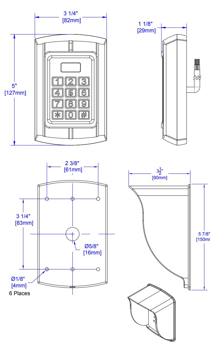
3. DIMENSIONS
Note: When the keypad is idle the LED is solid RED. In programming mode, the LED is flashing RED. The Master code for programming must be changed to configure any part of the CV-550SPK and its parameters. All changes must be done within programming mode.
| Enter Programming Mode |
Press the star (*) key for 2 seconds until it beeps then press
8 8 8 8 8 8 #. The LED will now be flashing Red. |
|
|---|---|---|
| Exit Programming Mode | Press the star key (*) to get a solid Red LED. | |
| Change Admin Password |
00 New 6-digit code #, New 6-digit code # (must be 6 digits).
The keypad cannot be configured until the Master Code has been changed from its default to any other 6-digit PIN. |
|
|
Power up while holding the * key. The LED will turn orange
and you will hear a double beep. |
||
| Default Master Code |
This will only default the Master Code for programming. All
other data will not be affected. |
|
| Restore Configuration to Factory Defaults |
For assistance call the Camden Technical Support line at
1-905-366-3377. |
|
| Delete All Users Card/PIN Data | Press 20 0000 # Deletes All User Card/PIN data. | |
| Stand-Alone Operation (All Card/PIN Data stored in the CV-550SPK V3) | ||
| Single Door Stand-Alone | 03 1 # Stand-Alone Mode | |
|
This refers to the memory address of where the Card or PIN
data is stored. It is not the PIN to unlock the door. |
||
| ID# |
Keep track of where data is stored to easily edit or delete any
individual record. |
|
| 10 Read Card # | ||
| Add a Card (Automatically Generates ID#) |
Multiple Entries 10 Read Card, Read Card, Read Card, Read
Card #. This will increment the ID# (storage location) by one for each card added. |
|
| 11 ID# (4-Digit PIN or Card) # | ||
|
Add a Card or PIN
(To a Specific ID#) |
Multiple Entries 11(ID) #, (User PIN or Card) #, (ID) #, (User
PIN or Card) # |
|
|
This will allow you to pick a unique ID # (storage location) to
add the card or PIN to. |
||
| Delete Card (by Reading) | 21 Read Card Multiple Deletes 21 Read, Read, Read, # | |
| Delete by ID# (Card or PIN) | 22 ID# # Multiple Deletes 22 ID# #, ID# #, ID# # | |
| 30 0 # (Card Only) Users must only use a Card or Tag. | ||
|
30 1 # (Card + PIN) Users must read their Card or Tag then
type in their PIN then #. |
||
| Door Access Mode |
Note: Press * for 2 seconds (beep), read card press 1234#,
New PIN then #, New PIN then #. |
|
|
30 2 # (Card or PIN) Users can use either their Card, Tag or
PIN number. |
||
| Unlock Duration | 34 (1-999 seconds) # | |
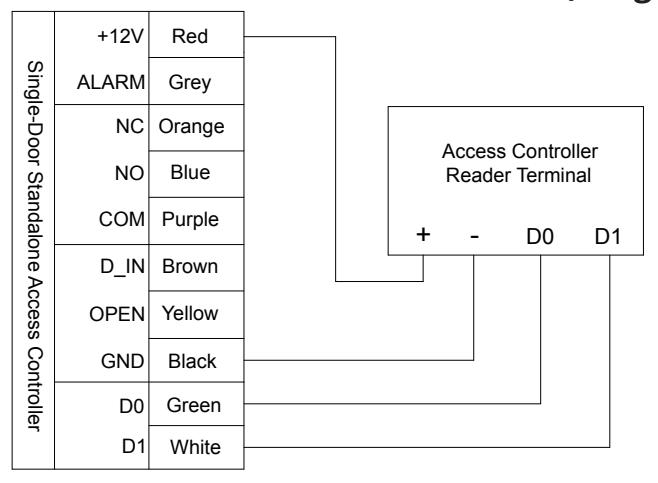
| Wiegand Out to Access System (Card/PIN stored in Access System) | ||
|---|---|---|
| Reader Mode |
Step 1) 03 0 #
(Enables data lines to be connected to an Access Controller) |
|
| Facility Code | Step 2) 60 (0-255) # (Must match Access Controller) | |
| Set D0 & D1 Output |
Step 3) 61 0 #
(Enables D0 & D1 Wiegand Output data format) |
|
| Set Output Bit Length | Step 4) 62 (26-66) # (Example of 26 bit: 62 26 #) | |
| PIN Output (5 Digits) | Step 5) 64 4 # (1–5-digit key + # key buffered output) | |
| Set 4/8 Bit Burst Output |
Step 6) 64 (0, 2) # (0 = 4 bit burst, 2 = 8 bit burst, confirm
with Access manufacturer) |
|
| Alarm Configuration (D.H.O/F.E.) | ||
| Door Held Open (D.H.O.) |
35 (0-99) # The set time starts once the door is unlocked, then
it will generate the alarm if the door is not closed. Timing is in minutes. Closing the door resets the alarm. |
|
| Door Forced Open (F.E.) 40 (0-99) # |
Door opened with no valid PIN or Card immediately triggers
an alarm. Timing is in minutes. Master Programming Code resets alarm. |
|
4. WIRING CONNECTIONS FOR DC OR AC POWER
The CV-550SPK V3 keypad can be powered by either DC or AC power within a range of 10V – 28V. When wiring for DC power use the red wire for positive and the black wire for ground. When wiring for AC power use the red wire (AC1) to one AC wire and light green wire (AC2) to the other AC wire.
Note: Confirm you are using the light green wire and not the dark green Data 0 wire.
Wiring for DC Power (AC1 & GND) Wiring for AC Power (AC1 & AC2)
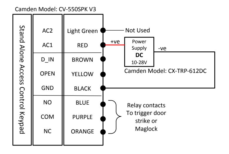
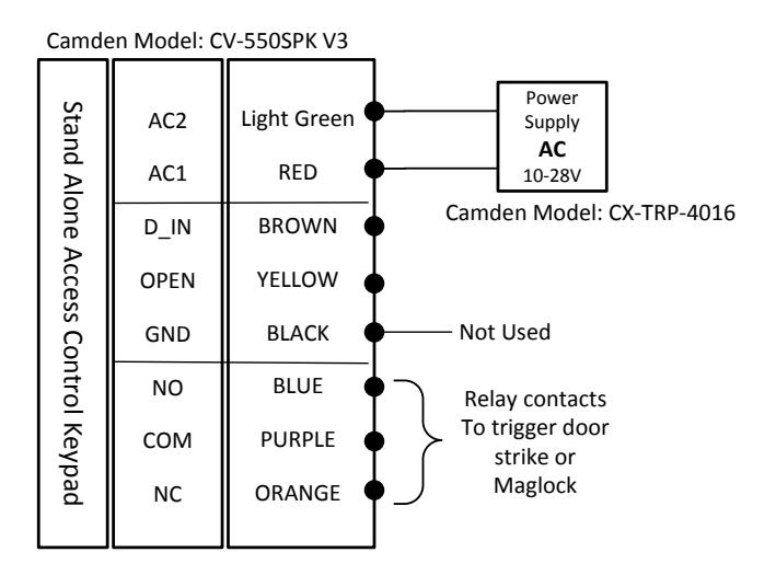
Note: Connect corresponding power as shown above to prevent damage to the keypad.
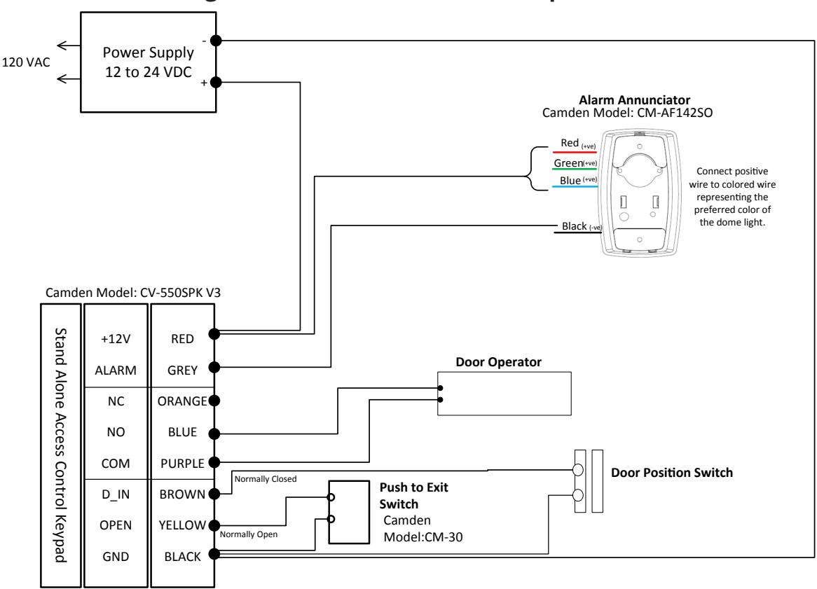
Wiring the CV-550SPK V3 to a Door Operator Wiring the CV-550SPK V3 to a door operator
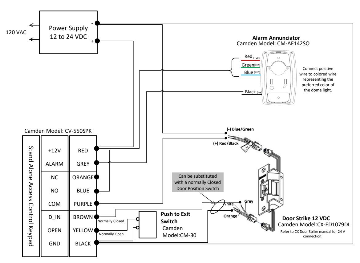
Wiring the CV-550SPK V3 to a Fail Secure Door Strike Wiring the CV‐550SPK V3 to a Fail Secure Door Strike
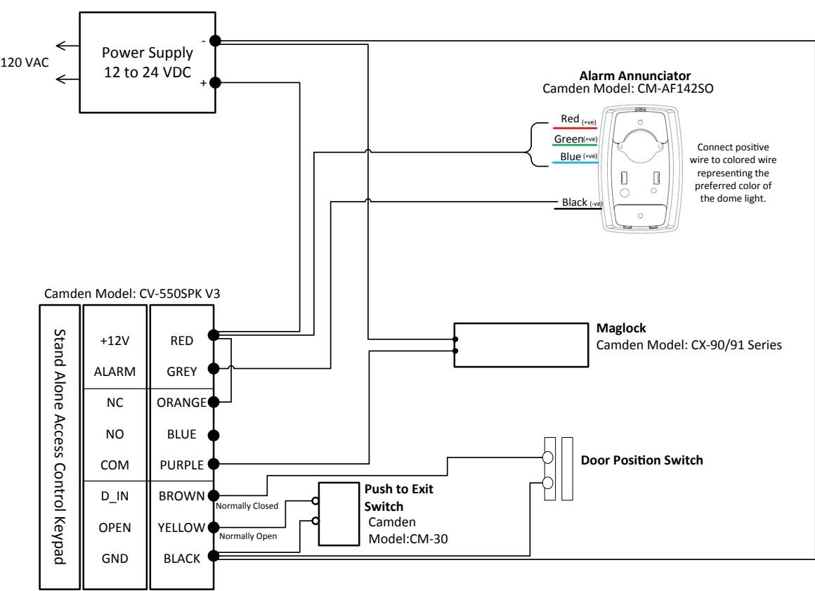
Wiring the CV-550SPK V3 to a Maglock Wiring the CV-550SPK V3 to a Maglock
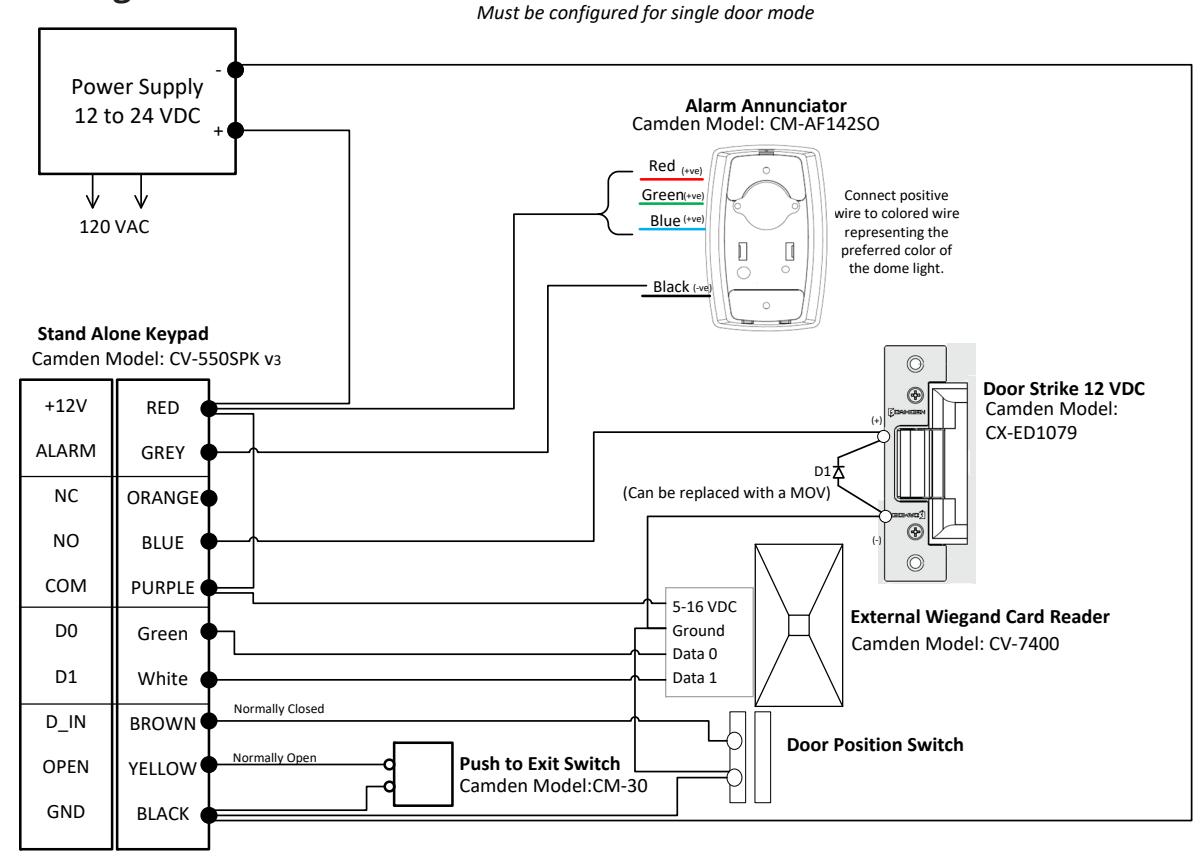
Wiring the CV-550SPK V3 to an External Card Reader and Door Strike Wiring the CV‐550SPK V3 to an external card reader and door strike
Wiring the CV-550SPK V3 to an Access Controller (Wiegand Out)
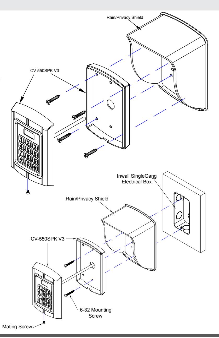
5. INSTALLATION
CV-550SPK V3 Wall Flush Mounting with Rain/Privacy Shield:
Note: Make necessary arrangements for wiring before Mounting the Keypad to the wall.
- Remove the mating screw located at the bottom of the keypad, allowing you to mount the keypad with the Rain/Privacy Shield to the wall.
- 2. Spot drill hole on the wall and take the supplied Self threading screws to tighten back of the Keypad to the Rain/Privacy Shield.
- 3. Place the front of the keypad onto the back of the keypad then tighten with the mating screw to keep keypad in place.
CV-550SPK V3 Inwall Electrical Box Flush Mounting with Rain/Privacy Shield:
Note: Thread the Keypad wire through the rain hood to make necessary arrangements for wiring before Mounting the Keypad.
- Remove the mating screw located at the bottom of the keypad, allowing you to mount the keypad with the Rain/Privacy Shield to the Electrical Box.
- 2. Take the supplied #6-32 screws and place it through the center top and bottom holes on the Keypad back plate, through the Rain/Privacy Shield then tighten screws to keep the plate and Rain/Privacy Shield onto the electrical box.
- 3. Place the front of the keypad onto the back of the keypad then tighten with the mating screw to keep keypad in place.
FCC ID: 2A48H-CV-550SPK
NOTE: This equipment has been tested and found to comply with the limits for a Class B digital device, pursuant to part 15 of the FCC Rules. These limits are designed to provide reasonable protection against harmful interference in a residential installation. This equipment generates, uses and can radiate radio frequency energy and, if not installed and used in accordance with the instructions, may cause harmful interference to radio communications. However, there is no guarantee that interference will not occur in a particular installation. If this equipment does cause harmful interference to radio or television reception, which can be determined by turning the equipment off and on, the user is encouraged to try to correct the interference by one or more of the following measures:
- • Reorient or relocate the receiving antenna.
- • Increase the separation between the equipment and receiver.
- • Connect the equipment into an outlet on a circuit different from that to which the receiver is connected.
- • Consult the dealer or an experienced radio/TV technician for help
For more comprehensive info refer to document: 40-82B306 CV-550SPK v3 Reference Manual