CM-SRFM2 Manual
Open the original PDF document
View PDF

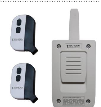
CM-SRFM2 Kit
Wireless 2 Channel Receiver with two transmitters
INSTALLATION INSTRUCTIONS
THIS PACKAGE INCLUDES:
(1) CM-SRX2 Receiver (2) Wall Plugs (used for mounting) (1) Grommet
(1) User Manual (2) Selft Tapping Screws (used for
(2) Transmitters CV-WTX2 mounting)
1. DESCRIPTION
The CM-SRFM2 is a wireless transmitter kit that includes two, 2 button transmitters and one 2 channel receiver. This kit will control up to two doors from one device. Ideal for front desk/reception applications or hard-to-wire locations. Designed to work with magnetic locks, electric strikes, keypads, gate operators and door operators. Kits include channel receiver and transmitter.
- Receiver can be mounted inside or outside. IP65 rated
- Rolling code encryption
- Field configurable latching/bi-stable mode keeps doors unlocked until button is pressed again
- Receiver can be controlled by up to 30 transmitters
- Receiver relay mode is either momentary or bi-stable for 2nd relay.
2. SPECIFICATIONS
| Input Power | 12V or 24V AC/DC | |
|---|---|---|
| Standby Current | 18mA (Input VDC12V) | |
| Operating Current | 80mA (Input VDC12V) | |
| Working Humidity | 0-95% | |
| Working Temperature | -20°C to 85°C (-4°F to 185°F) | |
| Lock Relay | 1A @ 30VDC | |
| Memory | 30 codes | |
| Encryption | High security rolling code. 19 trillion combinations | |
| Number of Relays | 2 relays; 1 ST relay momentary, 2 ND momentary or latching/bi-stable | |
| Frequency | 868.35 MHz | |
| IP Rating | 65 with grommet | |
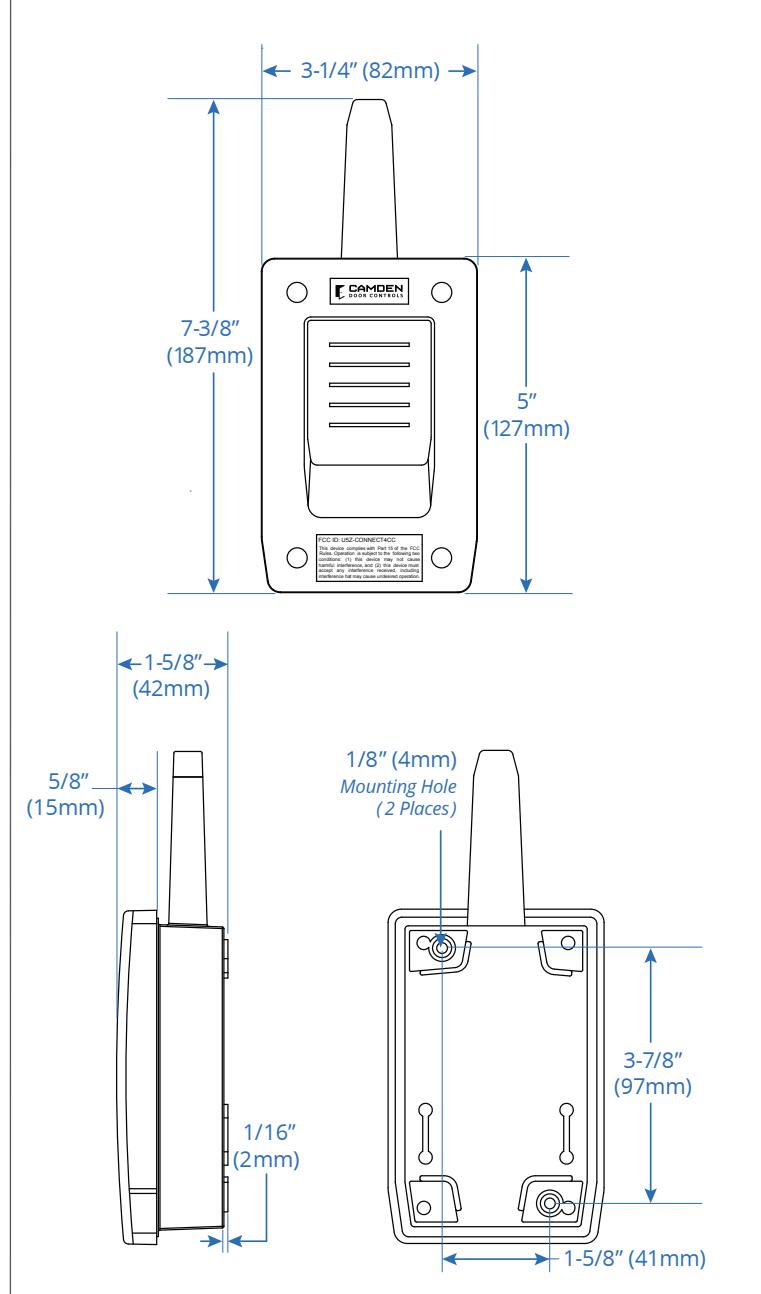
| Receiver Dimensions | 7-3/8" W x 3-1/4" H x 1-5/8" D (187mm x 82mm x 42mm) | |
| Transmitter Battery | CR3032 3 volt | |
| Transmitter Dimensions |
2" W x 3/16" H x 1" D
(55mm x 30mm x 10mm) |
|
3. DIMENSIONS
4. INSTALLATION
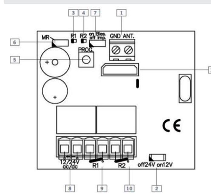
- 1. Antenna Connection 7. Microswitch Impulse/ Bi-Stable
-
2. Jumper 12/24V 8. Power Supply
-
3. Channel 1 Operation LED 9. Relay 1 Output
- 4. Channel 2 Operation LED 10. Relay 2 Output
- 5. Programming Push Button 11. Memory Card
- Connection
- 6. Jumper Reset
Attach the rear part of the housing to the wall using the plugs and screws supplied. Pass the cables through the bottom of the receiver. Connect the power cables to the 12/24V terminals marked on the PCB board as indicated. (Left terminal is positive) Seal and cover the receiver front cover to the base using the screws supplied.
5. OPERATION
The two red LED lights flash every 5 seconds to confirm power is applied to the receiver. Upon receiving a code, the receiver checks whether it is in its memory, activating the corresponding relay.
The relay activation mode is selected in either impulse or ON/OFF using the Imp/Bis jumper. Only relay 2 can have its mode changed by this jumper from momentary to bi-stable.
Changing the mode for relay 1 can only be accomplished at the factory. (Contact sales for details.)
6. PROGRAMMING
Manual programming
Press the receiver programming button for 1 sec. and an acoustic signal will be heard. The receiver will enter programming (see table below). If the receiver programming button is held pressed down, the receiver will sequentially go from one configuration to the next. Once the programming configuration for the transmitter to be registered has been chosen, send the code to be programmed by pressing the respective transmitter button (1 or 2). Every time a transmitter is programmed, the receiver will issue an acoustic signal for 0.5 seconds for confirmation. After 10 seconds without programming or pressing the first two transmitter buttons, the receiver will automatically exit programming mode while beeping one second twice. If upon programming a transmitter the receiver memory is full, the receiver will emit 7 beeps of 0.5 seconds and exit programming.
The receiver is always configured in multi-channel.
| Configuration of Transmitter Programming in the Receiver | LED R1 | LED R2 |
|---|---|---|
| The 1st relay is activated by channel 1 and the 2nd relay by channel 2 | Flashing | Flashing |
| Special Programming | ||
| Press the transmitter channel to activate the relay 1 on the receiver | ON | OFF |
| Press the transmitter channel to activate the relay 2 on the receiver | OFF | ON |
| Press the transmitter channel to activate the two relays at once * | ON | ON |
* If working in latching/bi-stable ON/OFF activation mode, relay 1 will act as impulse and relay 2 as ON/OFF. Therefore, on the first press relay 1 will close and open the contact and relay 2 will only close. On the second, relay 1 will close and open the contact and relay 2 will open.
NOTE: Each transmitter can be configured independently on the receiver.
Total Reset
In programming mode, press the programming button down and simultaneously short the "MR" jumper for 3 seconds. The receiver will issue 10 short acoustic warning signals followed by others at a faster pace to indicate that the operation has been successful. The receiver is now in programming mode. After 10 seconds without programming or quickly pressing the programming button, the receiver will exit programming mode, issuing two, one second beep signals.
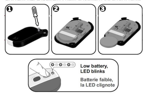
7. TRANSMITTER
NOTE: This equipment has been tested and found to comply with the limits for a Class B digital device, pursuant to part 15 of the FCC Rules. These limits are designed to provide reasonable protection against harmful interference in a residential installation. This equipment generates, uses and can radiate radio frequency energy and, if not installed and used in accordance with the instructions, may cause harmful interference to radio communications. However, there is no guarantee that interference will not occur in a particular installation. If this equipment does cause harmful interference to radio or television reception, which can be determined by turning the equipment off and on, the user is encouraged to try to correct the interference by one or more of the following measures:
- Reorient or relocate the receiving antenna.
- Increase the separation between the equipment and receiver.
- Connect the equipment into an outlet on a circuit different from that to which the receiver is connected.
- Consult the dealer or an experienced radio/TV technician for help