CM-RQE70 Manual
Open the original PDF document
View PDF

Door Activation Devices
CM-RQE70A PIR 'REQUEST TO EXIT' DETECTOR
INSTALLATION INSTRUCTIONS
THIS PACKAGE INCLUDES
- (2) #6 x 3/4" Screws
- (2) 3/16" Wall Plugs
- (2) MOV's

1. GENERAL DESCRIPTION
Camden CM-RQE70A Request-to-Exit Sensor is a passive infrared (PIR) detector designed for interior use. This device is UL listed as an access control device under UL 294 Standard and is listed for Class I for UL Canada under ULC-S319 when it is connected to a UL approved access control system.
2. FEATURES
- Compact size, designed to mount on door frames
- On-board programming buttons. No dip switches
- (4) factory default operating modes, with the ability to customize mode attributes
- Makes installation easy and fast
- Selectable Fail Safe/Fail Secure
- (2) Form 'C' contacts
- Momentary and latching relay modes
- Secondary activation device input
- Card/keypad input
- Door position switch input
- Request to exit input
- Built-in sounder (adjustable)
- Tamper switch
3. OPERATION
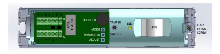
FIGURE 1 - COMPONENT LOCATIONS
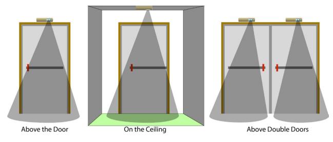
FIGURE 1 - MOUNTING LOCATIONS
Self-Test
When power is first applied to the CM-RQE70A, the sensor will beep once, then the unit performs a self-test to ensure its major functions are within acceptable operating parameters. The self-test checks the input voltage, switch operation and sensor function. If the sensor passes all tests, there is a single beep and normal operation begins. If the sensor fails any of the tests, the unit will provide a series of audible beeps indicating the failure. This is take approximately 30 seconds.
Post-Test Failure Beeps
If the sensor fails a test, the unit will perform one or more short beeps, followed by a long beep. This series of beeps is repeated continuously.
|
# of Short
Beeps |
Description |
|---|---|
| 1 |
The IR sensor did not settle to an acceptable level
during the test. |
| 2 |
One of the 3 buttons, Mode, Parameter or Select is
detected as being pressed. |
| 3 |
The Source Voltage to the CM-RQE70A is outside
of the range of 12 – 24V |
| 4 |
The IR sensor is not changing over a large enough
range of values to reach its settle point |
Fail Safe vs Fail Secure: Field Selectable
These terms are used to describe the normal operating state of the output relays. In Fail Safe Mode, the relays will be normally energized. The relays will de-energize when a person is in the field of view (normal operation) or when the power is removed due to an outage or other external reasons. In Fail Secure Mode, the relays remain de-energized normally. The relays will energize when a person is in the field of view (normal operation). The relays remain de-energized during a power outage, therefore, keeping the controlled device secure.
CM-RQE70A PIR 'REQUEST TO EXIT' DETECTOR
INSTALLATION INSTRUCTIONS
Tamper Switch
Dry contact outputs N/C are provided for interface to an alarm or access control systems. The Tamper Switch is connected to a spring that compresses and closes the switch when the housing cover is installed. Removing the cover will open the switch contacts providing a change in state to the monitoring system.
Indicator Lights: LED's
A Red & Green LED indicates secure vs unsecured status of the REX. The red LED is normally lit to indicate the door is secure. When a person walks within the detectable range of the sensor, the green LED will light and the red will be off.
Access Control Input
Input: Dry N/O A dry contact closure on this input allows a card reader or keypad on the secure side of the door to activate the REX sensor allowing access through the secured door.
Sounder Control
Input: Dry N/O A dry contact closure from an external device will hold this sounder on until it is released. The sounder will not affect the operation of the relays or relay timers.
Sequential Logic Input
Input: Dry This mode allows a secondary detection device to be connected to the REX sensor. The REX sensor is active only while this input is opened or for 10 seconds after it has closed. For example, when the secondary activation device is activated, the REX sensor functions normally. When a person is in the field of view, the sensor is activated and the door is released. If the secondary activation device is deactivated, the REX Sensor will continue to be activated if a person is in the field of view for an additional 10 seconds.
Door Monitor Contacts
Input: Dry
Operating Functions
Function 1: Latched
When the REX sensor is activated, the relay will remain active as long as the sensor is activated. Once the sensor is deactivated, the relay will remain on for the duration of the Relay On Time. If the door is opened, the Relay On Time is reduced to 2 seconds.
Function 2: Door Prop Open Alarm
The door contact input is used to monitor the status of the door. If the door is held open during the last 10 seconds of the timer relay set time, the sounder will annunciate until the door is closed again. If the door is opened without the REX being activated the sounder will annunciate until the door is closed or someone has moved into the REX Sensor's field of view.
Function 3: Unauthorized Access Mode
In this mode, when the REX sensor is activated but the door is not opened, the relay returns to a secured state in 10 seconds. If the REX sensor is activated and the door opens, then closes, the relay returns to secured state in 2 seconds.
Function 4: Timed
When the REX sensor is activated, the relay will remain active for the duration of the Relay On Time. Once the Relay On Time has expired, the relay drops out. If motion continues, the relay will activate for another full cycle. If the door is opened, the Relay On Time is reduced to 2 seconds.
External Disable/Enable
Input: Dry
In this mode, the REX is enabled or disabled by an external device, such as an access control system or security alarm panel. While this input is held open, the REX sensor will function normally. When this input is closed, the REX sensor operates the same as in Sequential Logic Input Mode.
Rex Sensor Default Modes
In an effort to make installation easier, we have defined different installation modes. These modes will cover 90+% of the applications. For the other 10%, there will be a Custom Mode where all settable functions can be adjusted.
Mode 1: Normal Latched REX Sensor
The most common mode, the sensor, when activated will enable the output relay for the duration of the Relay On Time (30 seconds). If a door contact is connected to Input #1, when the door is sensed to be opened, then closed, the Relay On Time is reduced to 2 seconds.
Relay On Time: 30s (If the door is opened and closed, the timer is
reduced to 2s)
Fail Mode: Fail Safe Operating Function: Latched PIR Sensitivity: 4 Sound Vol: 3
Input #1: Door Contact Input #2: Press to Exit Input #3: Sounder Input
Mode 2: Door Prop Alarm
The sensor monitors the status of the door. When activated, the sensor enables the output relay for 30 seconds. If the door is held open during the last 10 seconds of the Relay On Time, the piezo will sound until the door is closed. This mode requires a Door Contact to be connected to Input #1.
Relay On Time: 30s (If the door is opened and closed, the timer is
reduced to 2s) If the door is held open during the last 10 seconds of the relay on time, the piezo will
sound until the door is closed.
Fail Mode: Fail Safe
Operating Function: Door Prop Open Alarm
PIR Sensitivity: 4 Sound Vol: 3
Input #1: Door Contact Input #2: Press to Exit Input #3: Sounder Input
Mode 3: Access Control
The sensor will activate normally on motion. Input #3 is used to connect to an access control system. A contact closure on Input #3 will activate the sensor. A maintained closure on Input #3 will activate the sensor indefinitely.
Relay On Time: 0.5 sec (If the door is opened and closed, the timer
is reduced to 2s)
Fail Mode: Fail Safe Operating Function: Timed PIR Sensitivity: 4 Sound Vol: 3
Input #1: Door Contact Input #2: Press to Exit Input #3: Card Keypad
Mode 4: Secondary Activation Mode
The sensor requires activation of Input #3 before activating the output relay.
Relay On Time: 30s (If the door is opened and closed, the timer is
reduced to 2s)
Operating Function: Latched, Door Prop Open Alarm or Unauthorized
PIR Sensitivity: 4 Sound Vol: 3
Input #1: Door Contact Input #2: Press to Exit I Input #3: Sequential Input
In this mode, the sensor would behave as described above.
Mode 5: Custom Settings
The sensor may be programmed as required by the installation.
Relay On Time: 0.5, 1, 2.5, 5, 15, 30 45, and 60 seconds
(unauthorized mode is 10 sec)
Fail Mode: Fail Safe or Fail Secure
Operating Function: Latched, Door Prop Open, Unauthorized or Timed
PIR Sensitivity: 1 to 5 Sound Vol: 0 to 4
Input #1: Unused, Door Contact, Sounder Input, Sequential
Input, External Disable, Press to Exit, Card Keypad
Input #2: Unused, Door Contact, Sounder Input, Sequential
Input, External Disable, Press to Exit, Card Keypad
Input #3: Unused, Door Contact, Sounder Input, Sequential
Input, External Disable, Press to Exit, Card Keypad
4. INSTALLATION
Remove the sensor cover
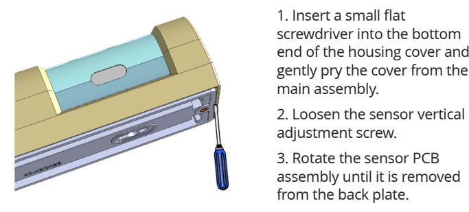
- 1. Insert a small flat end of the housing cover and gently pry the cover from the
- assembly until it is removed from the back plate.
Install the Back Plate
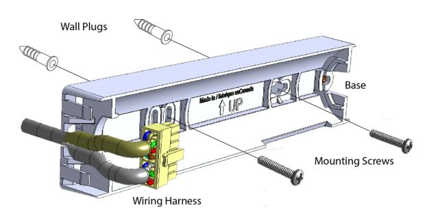
- 1. Using a 3/16" drill, drill 2 mounting holes 3 ¼" apart at the desired height of installation.
- 2. Insert the 2 x 3/16" wall plugs into the holes
- 3. Align the sensor back plate with the mounting holes and screw in the 2 x #6 screws, securely fastening the sensor back plate to the wall.
- 4. Rotate the sensor PCB assembly into the back plate.
Wiring the Sensor
The Camden CM-RQE70A uses a plug-in wiring harness for all electrical connections. The Pin out is described below.
| J2 | Description | |
|---|---|---|
| 1 | Power + | |
| 2 | Input 1 | |
| 3 | Input 2 | |
| 4 | Input 3 | |
| 5 | Ground | |
| 6 | Tamper Switch 1 | |
| 7 | Tamper Switch 2 | |
| J4 | Description | |
| 1 | Relay 1b – Normally Closed (NC2) | |
| 2 | Relay 1b – Normally Open (NO2) | EMF spike |
| 3 | Relay 1b – Common (C2) | protected relay |
| 4 | Relay 1a – Normally Closed (NC1) | |
| 5 | Relay 1a – Normally Open (NCO1) | |
| 6 | Relay 1a – Common (C1) |
Adjusting the Sensor Detectable Range
The sensor's detectable range can be adjusted vertically and horizontally.
Horizontal Adjustment
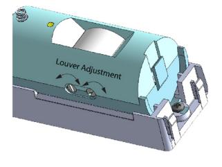
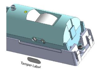
The horizontal adjustment of the sensor is accomplished by adjusting the 2 louvers inside the lens area. The louvers are adjusted using a small flat head screwdriver. On the bottom of the sensor housing there are 2 adjustment screws. Turning the screws adjusts the louvers left and right horizontally, therefore changing the beam direction and width. Once the horizontal adjustment is complete, place the tamper label (provided) over the set screws to avoid accidental adjustment.
Vertical Adjustment
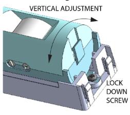
The sensor beam is vertically adjusted by rotating the PCB assembly barrel within the mounting back plate. Once the vertical adjustment is complete, tighten the lock down screw to prevent the barrel from moving.
Once all adjustments are made, install the sensor cover and install the set screw provided.
CM-RQE70A PIR 'REQUEST TO EXIT' DETECTOR
INSTALLATION INSTRUCTIONS
Programming Buttons
There are no DIP switches to set on this Rex Sensor. 3 buttons are used for all setup and programming.
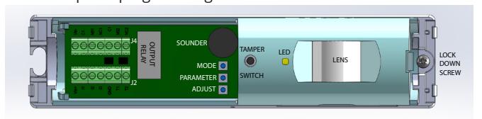
The MODE Button (top):
The MODE button is used to select 1 of 4 pre-set modes or a fully configurable custom Mode. Pressing the MODE button for the first time will indicate which Mode the REX sensor is currently in. The REX sensor will BEEP and the LED will flash red the number of times equal to the MODE number. I.E. 1 Beep/Flash = Mode 1.
The Parameters Button (Middle)
This button selects the available parameters in each mode that can be customized. From within any Mode, press this button to cycle through the parameters.
| Mode | Beeps |
Red
LED Flashes |
Description |
|---|---|---|---|
| 1 | 1 | 1 | Latched Mode |
| 2 | 2 | 2 | Door Prop Alarm Mode |
| 3 | 3 | 3 | Access Control Mode |
| 4 | 4 | 4 | Secondary Activation Mode |
| 5 | 5 | 5 | Custom Settings Mode |
The Adjust Button (Bottom)
The adjust button is used to change the value of the Parameter. Once a Parameter is selected, use the Adjust button to cycle through the available options for each parameter as described in the below table.
| Parameter | 1 beep | 2 beeps | 3 beeps | 4 beeps | 5 beeps | 6 beeps | 7 beeps | 8 beeps | LED |
|---|---|---|---|---|---|---|---|---|---|
|
Relay On
Time |
0.5 | 1 | 2.5 | 5 | 15 | 30 | 45 | 60 | Yellow Solid |
| Fail Mode | Safe | Secure |
Red/Yellow
Flashing |
||||||
|
Operation
Mode |
Latched |
Door Prop
Open Alarm |
Unauthor-
ized Access |
Timed |
Green/Yel-
low Flashing |
||||
|
PIR
Sensitivity |
1 | 2 | 3 | 4 | 5 |
Red/Green
Flashing |
|||
|
Sound
Volume |
0 | 1 | 3 | 3 | 4 |
Red/Green/
Yellow Flashing |
|||
| Input #1 | Unused | Press to Exit |
Card/
Keypad |
Door
Contact |
Sounder
Input |
Sequential
Input |
External
Disable |
External
Disable |
Red
Flashing |
| Input #2 | Unused | Press to Exit |
Card/
Keypad |
Door
Contact |
Sounder
Input |
Sequential
Input |
External
Disable |
External
Disable |
Green
Flashing |
| Input #3 | Unused | Press to Exit |
Card/
Keypad |
Door
Contact |
Sounder
Input |
Sequential
Input |
External
Disable |
External
Disable |
Yellow
Flashing |
Factory Reset
The Camden CM-RQE70A Request to Exit sensor can be reset to factory defaults by pressing and holding the MODE and Adjust buttons. The Sensor will start to beep. Continue holding the MODE and ADJUST buttons while the beeping gets progressively faster until it reaches a steady tone. When the tone stops, the REX sensor has been reset to factory defaults and the MODE and ADJUST buttons may be released.
Regulatory Information
The unit shall be installed in accordance with National Electrical Code ANSI/NFPA 70 and part 1 of the Canadian Electrical Code CSA C22.1, Safety Standard for Electrical Installations and authorities having jurisdiction (AHJ's).
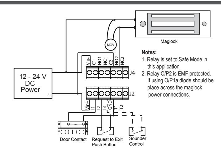
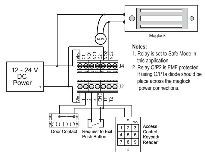
MODE 1&2 WIRING DIAGRAM
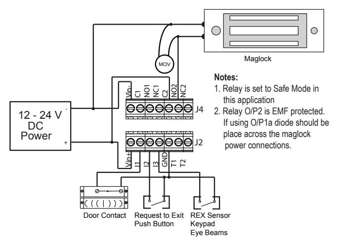
MODE 3 WIRING DIAGRAM
| J2 | Description | |
|---|---|---|
| 1 | Power + | |
| 2 | Input 1 | |
| 3 | Input 2 | |
| 4 | Input 3 | |
| 5 | Ground | |
| 6 | Tamper Switch 1 | |
| 7 | Tamper Switch 2 | |
| J4 | Description | |
|
J4
1 |
Relay 1b - Normally Closed (NC2) | EME Snike |
| EMF Spike | ||
| 1 | Relay 1b - Normally Closed (NC2) | EMF Spike protected relay |
| 1 |
Relay 1b - Normally Closed (NC2)
Relay 1b - Normally Open (NO2) |
EMF Spike protected relay |
| 1 2 3 |
Relay 1b - Normally Closed (NC2)
Relay 1b - Normally Open (NO2) Relay 1b - Common (C2) |
EMF Spike protected relay |
|
1
2 3 4 |
Relay 1b - Normally Closed (NC2)
Relay 1b - Normally Open (NO2) Relay 1b - Common (C2) Relay 1a - Normally Closed (NC1) |
EMF Spike protected relay |
MODE 4 WIRING DIAGRAM
5. SPECIFICATIONS
Voltage: 12 /24V DC operation Current Draw: 50mA (max) Relays: (2) Form 'C' (DPDT) 3A @ 30VDC Contact Rating: On-board push buttons Programming: and status LED Modes: - (4) Factory Default
- (1) Fully Custom - Selectable Fail Safe/
Fail Secure
- Max. 10' W x 10' H Coverage:
- Horizontal & vertical adjustment (mechanical) - Sensor sensitivity/range
(electronic)
Time Delay: Adjustable, 0.5, 1, 2.5, 5, 15, 30, 45 & 60
Sounder: On/Off, with adjustable
volume
Piezo Buzzer: 92db.@ 10cm.
Indicator: Activation LED
Card or
Keypad Input: (1) N/0
Door Position Switch Input:
(1) N/0
Request to
Exit Input: (1) N/0
Tamper Switch
Contact Rating: 50mA @ 12VDC
Temp Operating
Range: 32°F - 120°F (0 - 50°C)
Humidity Range: 0 - 93% non-condensing Dimensions: 13/4"H x 7" W x 13/4" D
(43mm x 176mm x 43mm)
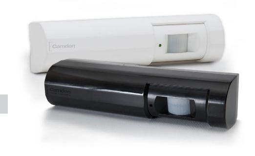
Weight: 0.25 lbs. (0.12kg.) White and black models Colors:
UL 294 Access Control Performance Levels
- 1) Access Controls, Destructive Attack Level I (No Attack)
- 2) Line Security Level I (No Line Security)
- 3) Endurance Level IV (100,000 cycles)
- 4) Standby Power Level I (No Stand by Power)
Power is to be supplied by a compatible UL294 Listed control unit, or by a UL294 Listed or UL603 Listed Class 2 low-voltage power limited power supply that is capable of 4 hours of standby power, as described in the installation guide.
The products shall not be installed in the fail-secure mode unless permitted by the local authority having jurisdiction and shall not interfere with the operation of Listed panic hardware.
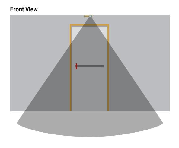
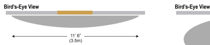
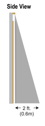
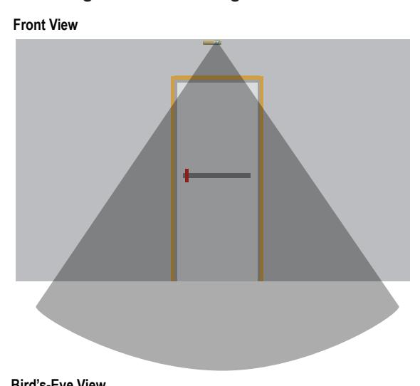
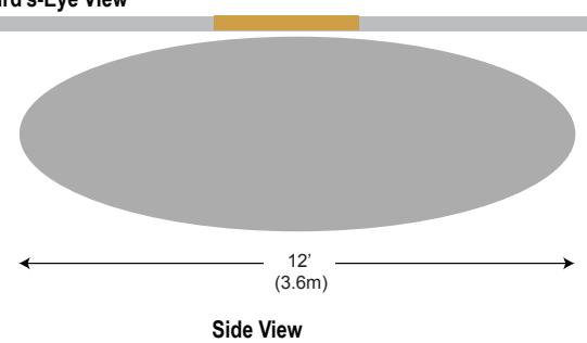
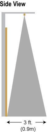
6. COVERAGE INFORMATION
The detection area changes depending on the mounting height and angle of the lens of the REX sensor. If the REX sensor is mounted on the wall above a door with the lens pointing straight, the detection areas against the wall are not detected and not shown in the illustrations. Mounting the REX sensor at higher heights,results.
in a larger detection area typically. The illustrations show the REX sensor mounted at 7.5 (2.3m) Feet on a wall with the lens pointing straight down and at 8 Feet (2.4m) on a ceiling with the lens pointing straight down.
7'5" Ceiling - Above Single Door 8' Ceiling - Over the Ceiling