CM-9800 Manual
Open the original PDF document
View PDF

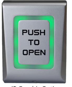
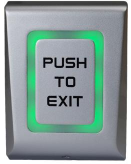
Door Activation Devices
CM-9800
Touch Button Switch
INSTALLATION INSTRUCTIONS
| SL NO | Component Name | Quantity | |
|---|---|---|---|
| 1 | Wall plug 6mm | 3 | |
| 2 | Wall fixing screw 4 x 30mm | 3 | |
| 3 | 3 x 6 Security Screw | 1 | |
| 4 | IN4007 diode | 1 | |
| 5 | 470nf Capacitor | 1 | |
| 6 | 10K Res 1/2w | 1 | |
| 7 | Security screw driver | ||
| 8 | 6-32 x 1" Machine screw | 2 | |
| 9 | Mounting Template | 1 | |
1. GENERAL DESCRIPTION
CM-9800 is a request-to-exit switch, It will work independently (standalone) or can equally be connected via a controller to provide exit from a secured area (Push Button Input). With its slim looks and die-cast metal body, the CM-9800 combines elegance and aesthetics with ruggedness and reliability.
2. SPECIFICATIONS
| Input Voltage | 12-24V AC/DC | ||
|---|---|---|---|
| Current Consumption | Max. 65mA | ||
| Relay Output | 2A at 24V DC / 120V AC | ||
| Set Relay Time | 0.5 to 60 seconds or Toggle (ON/OFF) | ||
| Indicators-LED | Orange, red, green | ||
| LED Control | Yes, by DIP switch | ||
| Tamper | Yes | ||
| Backlight ON/OFF | Yes, by DIP switch | ||
| Buzzer ON/OFF | Yes, by DIP switch | ||
|
Operating
Temperature |
-4°F to 122°F (-20°C to 50°C) | ||
| Operating Humidity | Non-condensing up to 95% | ||
| Housing | Die-cast Aluminium alloy | ||
| Touch Plate | Mild Steel Painted | ||
| Protection | IP66 | ||
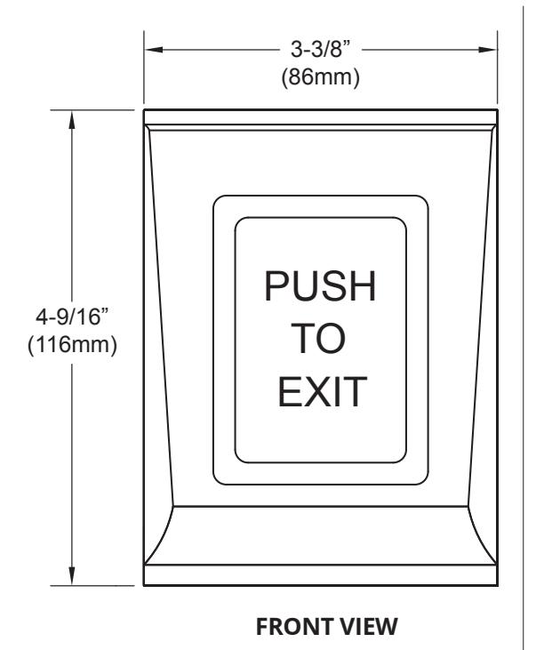
| Dimension |
3.34" W x 4.5" L x 1/32" H
(85mm x 116.6mm x 22.6mm) |
||

/3 Graphic Option /7 Graphic Option
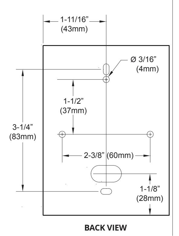
3. MOUNTING
- 1. Identify a suitable location on wall or flat surface.
- 2. Stick the Drilling Template provided on chosen location. Drill 3 holes as indicated in the diagram.
- 3. Insert 3 nos. of 6 mm wall plugs provided into the drilled holes.
- 4. Route the cables through the holes provided in the BackPlate.
- 5. Fix the Backplate firmly on the wall using 3nos. of 4 x 30mm CSK screws
- 6. Connect wires.
- 7. After wiring, place the Housing over the fixed backplate and guide the slot into the backplate tab and slide it downwards.
- 8. Fix the Housing to the Back-Plate with a M3 x 6 mm Security Screw on the bottom of the Housing using a Security Screwdriver provided.
Important Note: Several layers of protection are provided against transient voltages from static discharge, lightning and power supply spikes. For protection to be fully effective, earth grounding should be done correctly.
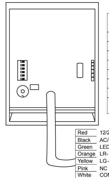
Purple Grey Blue
Tamp
| Color | |||||
|---|---|---|---|---|---|
|
12/24 V
AC/DC |
12 to 24VDC
12 to 24VAC |
Black &
Red |
|||
| Tamp | Tamper Switch | Grey | |||
| Tamp | Tamper Switch | Blue | |||
| LR | Red LED light | Orange | |||
| LG | Green LED light | Yellow | |||
| NC | Normally closed | Pink | |||
| COM | Common | White | |||
| NO | Normally open | Purple | |||
|
LED com
(GND) |
LED common | Green | |||
|
12/24V
Power Supply AC/DC LED com (GND) LR LG NC COM Relay 2A NO Tamp |
|||||
Tamper
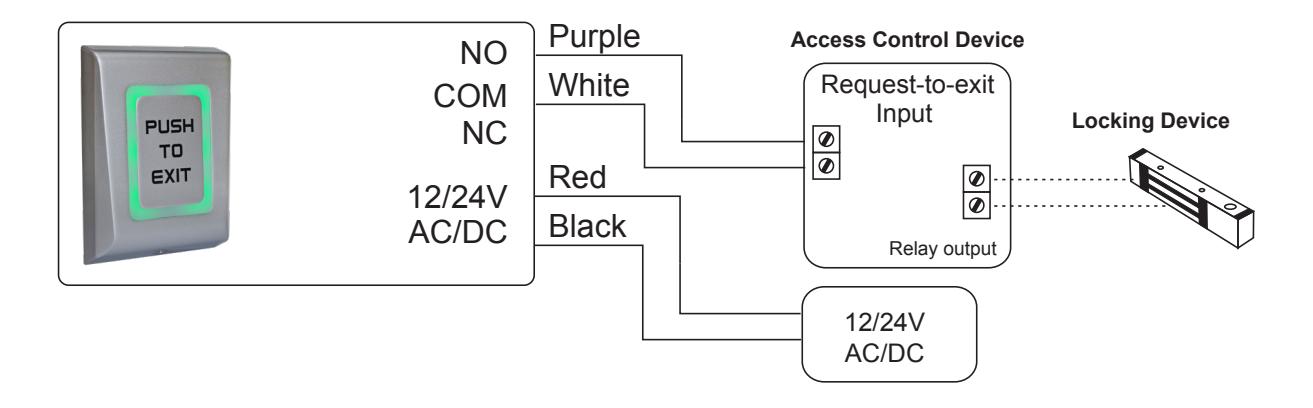
CONNECTION TO ACCESS CONTROL PANEL
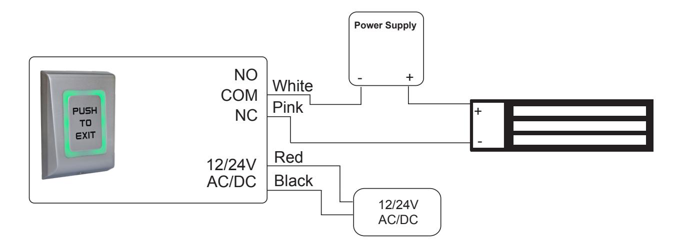
OUTPUT CONNECTION FOR DC DEVICE - FAIL OPEN
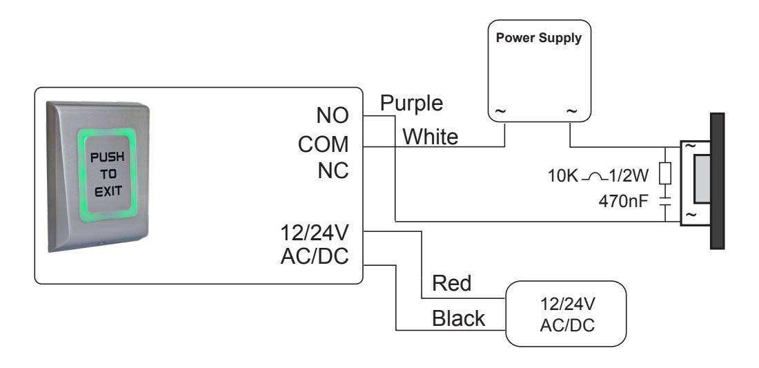
OUTPUT CONNECTION FOR AC DEVICE - FAIL SECURE
DIP SWITCH SETTINGS
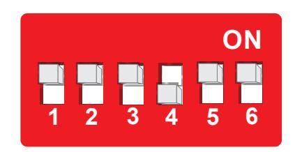
- 1 Relay Time (0.5 to 60 seconds or toggle mode)
- 2 not used
- 3 Buzzer ON/OFF
- 4 Backlight ON/OFF
- 5 LED Control
- 6 Default state State of the controller's input for the LEDs
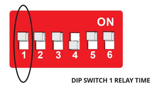
SET RELAY TIMER – DIP SWITCH 1
CM-9800 operates in Toggle or Pulse mode. The time is set by Dipswitch 1 Setting .
Put the Switch 1 in position ON. The unit will start emitting beeps. Count the beeps and then stop them by positioning the Switch 1 to OFF. The number of beeps defines the relays time, according to the table below (2 beeps - 0.5 sec, 3 beeps - 1 sec...).
| Switch 1 | Number of Beeps | Time | ||
|---|---|---|---|---|
| ON | 1 beep |
Toggle Mode
(ON/OFF Mode) |
||
| ON | 2 beeps | 0.5 Seconds | ||
| ON | 3 beeps | 1 Seconds | ||
| ON | 4 beeps | 2 Seconds | ||
| ON | 5 beeps | 5 Seconds | ||
| ON | 6 beeps | 10 Seconds | ||
| ON | 7 beeps | 15 Seconds | ||
| ON | 8 beeps | 30 Seconds | ||
| ON | 9 beeps | 45 Seconds | ||
| ON | 10 beeps | 60 Seconds | ||
BUZZER, BACKLIGHT AND LED CONTROL
Position 3, 4, 5, and 6 On Dip Switch
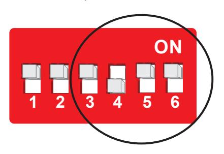
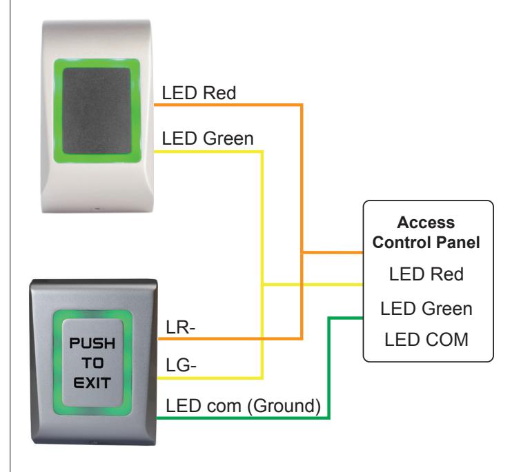
Example of externally controlled LED light, where the exit button's light follows the reader's light.
| SW3 | Buzzer | SW 4 |
SW 5
LED Control |
SW 6
Default State |
Relay | Green-Yellow |
Red-Orange
Wire |
Backlight |
|---|---|---|---|---|---|---|---|---|
| Backlight | LED Control | Default State | Wire | vvire | ||||
| ON | ON | - | - | - | - | - | - | - |
| OFF | OFF | - | - | - | - | - | - | - |
| - | - | OFF | OFF | - | ON | - | - | Green |
| - | - | OFF | OFF | - | OFF | - | - | No Light |
| - | - | ON | OFF | - | ON | - | - | Green |
| - | - | ON | OFF | - | OFF | - | - | Red |
| Default Hig | gh | |||||||
| - | - | ON | ON | OFF | - | Hi | Hi | Orange |
| - | - | ON | ON | OFF | - | Low | Hi | Green |
| - | - | ON | ON | OFF | - | Hi | Low | Red |
| - | - | ON | ON | OFF | - | Low | Low | No Light |
| Default Hig | gh | |||||||
| - | - | OFF | ON | OFF | - | Hi | Hi | No Light |
| - | - | OFF | ON | OFF | - | Low | Hi | Green |
| - | - | OFF | ON | OFF | - | Hi | Low | Red |
| - | - | OFF | ON | OFF | - | Low | Low | Orange |
| Default Lo | w | |||||||
| - | - | ON | ON | ON | - | Hi | Hi | No Light |
| - | - | ON | ON | ON | - | Low | Hi | Green |
| - | - | ON | ON | ON | - | Hi | Low | Red |
| - | - | ON | ON | ON | - | Low | Low | Orange |
| Default Low | ||||||||
| - | - | OFF | ON | ON | - | Hi | Hi | Orange |
| - | - | OFF | ON | ON | - | Low | Hi | Red |
| - | - | OFF | ON | ON | - | Hi | Low | Green |
| - | - | OFF | ON | ON | - | Low | Low | No Light |
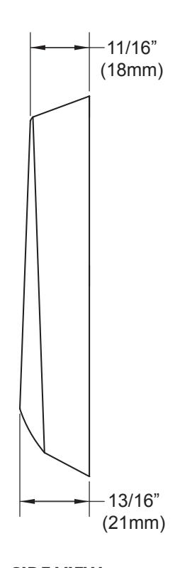
SIDE VIEW