CM-550SK V3 Manual
Open the original PDF document
View PDF

Door Activation Devices
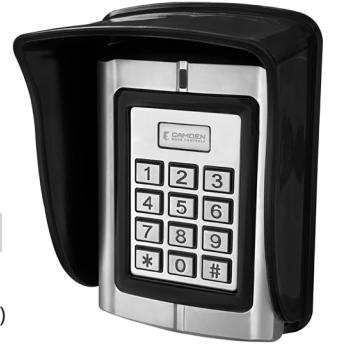
CM-550SK V3 Waterproof Keypad/Controller
INSTALLATION INSTRUCTIONS
THIS PACKAGE INCLUDES:
(1) Digital Keypad CM-550SK V3
(4) Wall plugs
(1) User Manual
(6 x 27 mm, used for mounting)
(1) Screw driver
(4) Self tapping screws (3.5 x 27 mm, used for mounting)
1. DESCRIPTION
The CM- 550SK V3 is a back-lit single door multifunction standalone access control keypad with a Wiegand input/output interface. It is suitable for mounting either indoors or outdoors in harsh environments. It is housed in a strong, sturdy and vandal proof Zinc Alloy electroplated case. The electronics are fully potted so the CM-550SK V3 is waterproof and conforms to IP68.
The CM-550SK V3 supports up to 20,000 Users. The PIN output data can be configured for either 26 bit, 4-bit or 8-bit burst modes making it compatible with most Access systems. These features make the CM-550SKV3 an ideal choice for door access for commercial and industrial applications such as factories, offices, warehouses, laboratories, banks, and prisons.
2. SPECIFICATIONS
| Input Power | 10-28V AC/DC |
|---|---|
| Standby Current | 35mA (Input VDC12V) |
| Operating Current: | 100mA (Input VDC12V) |
| Working Humidity | 0-95% |
|
Working
Temperature |
-40°C to 60°C (-40F to 140F) |
|
Alarm Output
(Digital) |
1A @ 30VDC |
| Lock Relay | 1A @ 30VDC |
| IP Rating | 68 |
Note: When the keypad is idle the LED is solid RED. In programming mode, the LED is flashing RED. The Master code for programming must be changed to configure any part of the CM-550SK and its parameters. All changes must be done within programming mode.
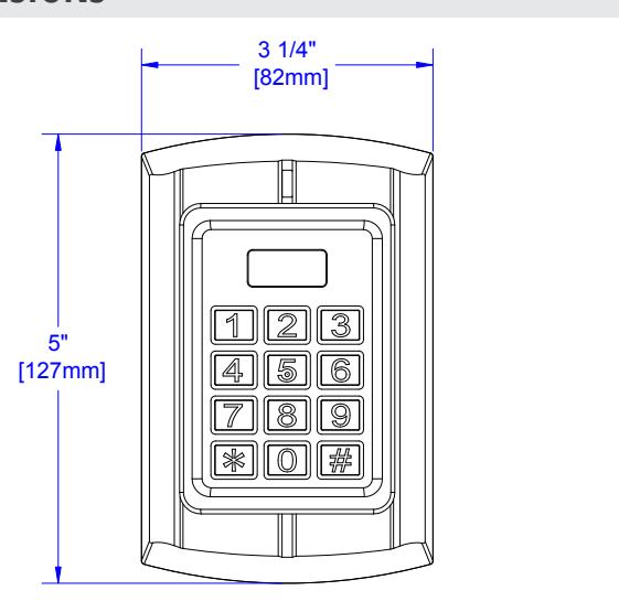
3. DIMENSIONS
4. OPERATION CONVENTIONS
- "Beep-" One long beep means the operation was correct. "Beepbeep-beep" three short beeps mean the operation was incorrect. The LED light turns green when the operation is successful.
- "#" means the previous operation was received by the system. It is normally used at the end of entering digital numbers for a PIN code, ID number, card number, or parameter. When you type this key, the programming is finished.
- "*" means to cancel the current operation or go back to the previous menu.
- The management menu is fixed to 2 digits, from 00 to 99. Do not press "#" on the keypad afterwards. After entering the 2 digits, the LED will turn orange (or purple). If the operation fails, you will hear "beep-beep-beep" three short beeps.
- Under the management menu operation mode, if there is no activity detected of keys being pressed for over 30 seconds, it will automatically revert to standby mode.
Indicator light and buzzer prompt
| Operation Status | Indicator light | Buzzer |
|---|---|---|
| Standby mode | Red | |
| Successful operation | Green | A long beep |
| Operation incorrect | 3 short beeps | |
| Press digit key | A short beep | |
| Press * key | A long beep | |
| Inputting opening door PIN | Red slow flash | |
| The first unlock | Green | |
| Alarm | Red quick flash | Alarm Sound |
| Enter Programming Mode |
Press the star (*) key for 2 seconds until it beeps then press
8 8 8 8 8 8 #. The LED will now be flashing Red. |
||
|---|---|---|---|
| Exit Programming Mode | Press the star key (*) to get a solid Red LED. | ||
| Change Admin Password |
00 New 6-digit code #, New 6-digit code # (must be 6 digits).
The keypad cannot be configured until the Master Code has been changed from its default to any other 6-digit PIN. |
||
| Default Master Code |
Power up while holding the * key. The LED will turn orange
and you will hear a double beep. This will only default the Master Code for programming. All other data will not be affected. |
||
| Restore Configuration to Factory Defaults |
For assistance call the Camden Technical Support line at
1-905-366-3377. |
||
| Delete All Users PIN Data | Press 20 0000 # Deletes All User Card/PIN data. | ||
| Stand-Alone Operation (PIN Data stored in the CM-550SK V3) | |||
| Single Door Stand-Alone | 03 1 # Stand-Alone Mode | ||
|
This refers to the memory address of where the Card or PIN
data is stored. It is not the PIN to unlock the door. |
|||
| ID# |
Keep track of where data is stored to easily edit or delete any
individual record. |
||
| 11 ID# (4-Digit PIN or Card) # | |||
| Add a PIN (To a Specific ID#) |
Multiple Entries 11(ID) #, (User PIN or Card) #, (ID) #,
(User PIN or Card) # |
||
|
This will allow you to pick a unique ID # (storage location) to
add the PIN to. |
|||
| Delete by ID# (Card or PIN) | 22 ID# # Multiple Deletes 22 ID# #, ID# #, ID# # | ||
|---|---|---|---|
| Unlock Duration | 34 (1-999 seconds) # | ||
| Wiegand Out to Access System (Card/PIN stored in Access System) | |||
| Wiegand Output Mode |
Step 1) 03 0 #
(Enables data lines to be connected to an Access Controller) |
||
| Facility Code | Step 2) 60 (0-255) # (Must match Access Controller) | ||
| Set D0 & D1 Output |
Step 3) 61 0 #
(Enables D0 & D1 Wiegand Output data format) |
||
| Set Output Bit Length | Step 4) 62 (26-66) # (Example of 26 bit: 62 26 #) | ||
| PIN Output (5 Digits) | Step 5) 64 4 # (1–5-digit key + # key buffered output) | ||
| Set 4/8 Bit Burst Output |
Step 6) 64 (0, 2) # (0 = 4 bit burst, 2 = 8 bit burst, confirm with
Access manufacturer) |
||
| Alarm Configuration (D.H.O/F.E.) | |||
| Door Held Open (D.H.O.) |
35 (0-99) # The set time starts once the door is unlocked, then
it will generate the alarm if the door is not closed. Timing is in minutes. Closing the door resets the alarm. |
||
| Door Forced Open (F.E.) |
40 (0-99) # Door opened with no valid PIN or Card
immediately triggers an alarm. |
||
| Timing is in minutes. Master Programming Code resets alarm. | |||
5. WIRING CONNECTIONS FOR VDC OR VAC POWER
The CM-550SK V3 keypad can be powered by either VDC or VAC power within a range of 10V – 28V.
When wiring for VDC power use the red wire for positive and the black wire for ground.
When wiring for VAC power use the red wire (AC1) to one VAC wire and light green wire (AC2) to the other VAC wire.
Note: Confirm you are using the light green wire and not the dark green Data 0 wire.
Wiring for DC Power (AC1 & )DNG gniriW for AC Power (AC1 & AC2)
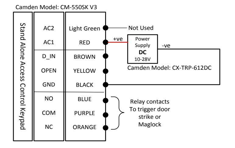
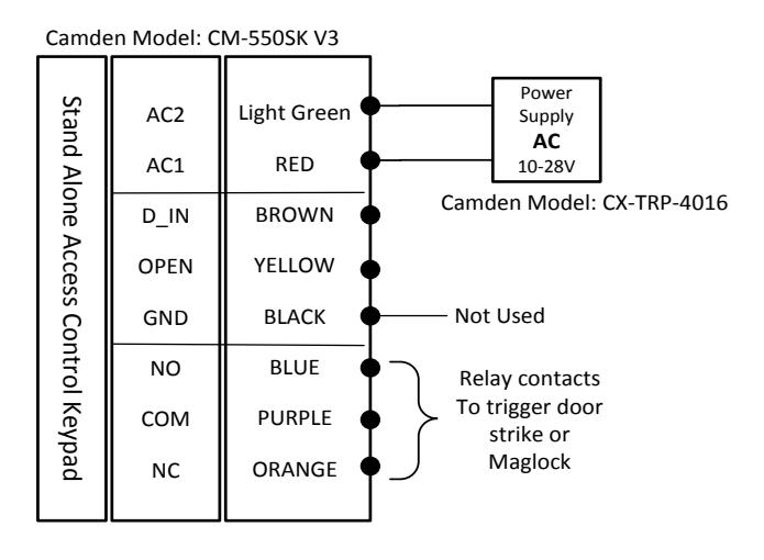
Note: Connect corresponding power as shown above to prevent damage to the keypad.
Keypad
OPEN GND
YELLOW BLACK
Normally Open
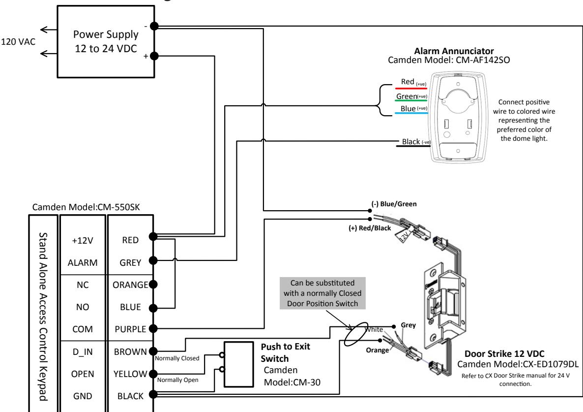
Power Supply 12 to 24 VDC Stand Alone Access Control +12V ALARM NC NO COM D_IN RED GREY ORANGE BLUE PURPLE BROWN Blue Alarm Annunciator Connect positive wire to colored wire representing the preferred color of the dome light. Camden Model: CM-AF142SO (+ve) Push to Exit Black (-ve) Red (+ve) (+ve) Door Operator Normally Closed Camden Model: 120 VAC Wiring the CM-550SK V3 to a door operator Door Position Switch CM-550SK V3 Wiring the CM-550SK V3 to a Door Operator
Wiring the CM-550SK V3 to a Fail Secure Door Strike Wiring the CM-550SK V3 to a Fail Secure Door Strike
Switch Camden Model:CM-30
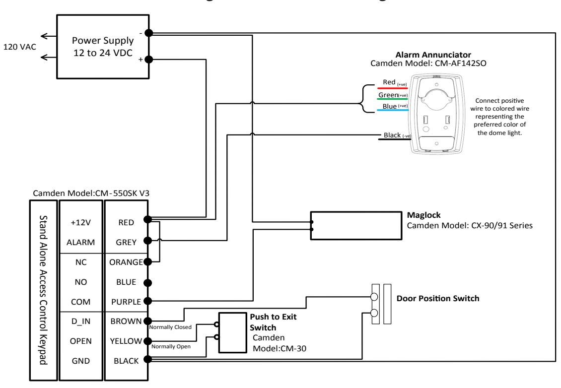
Wiring the CM -550SK V3 to a Maglock Wiring the CM-550SK V3 to a Maglock
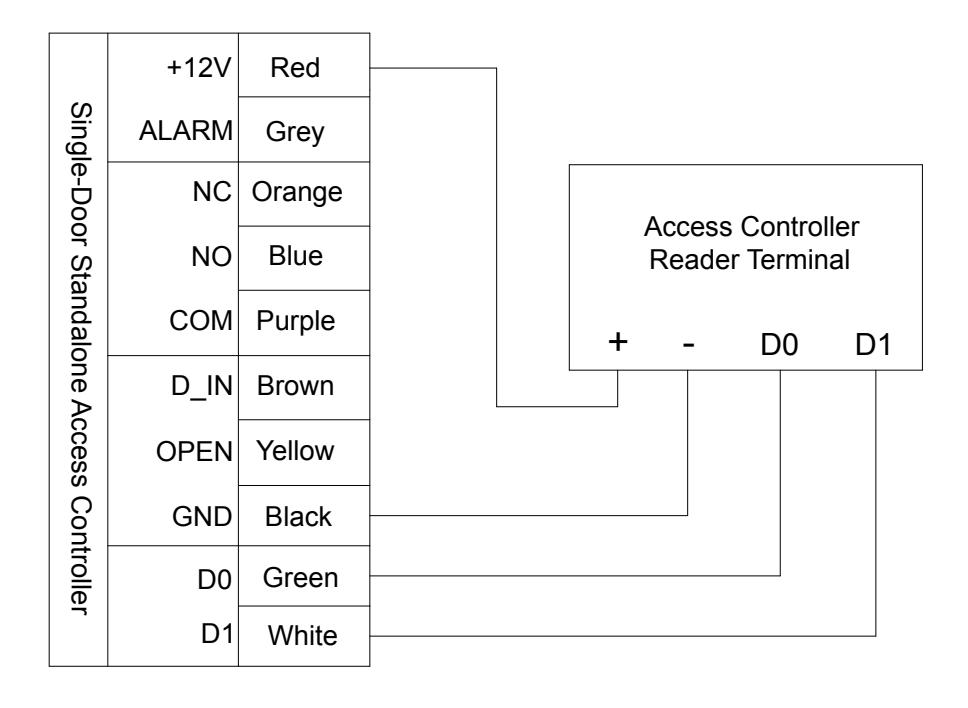
Wiring the CM-550SK V3 to an Access Controller (Wiegand Out)
Call: 1.877.226.3369 / 905.366.3377 Visit: www.camdencontrols.com