CM-3200, CM-3500 Manual
Open the original PDF document
View PDF

Door Activation Devices
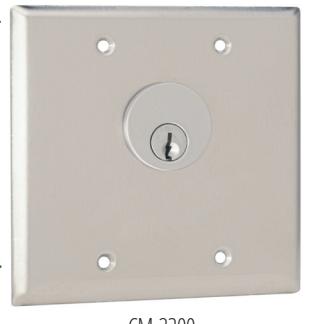
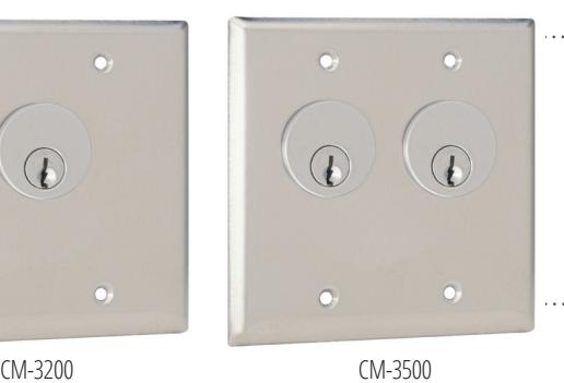
CM-3200 & 3500 Series Stainless Steel Key Switches
INSTALLATION INSTRUCTIONS
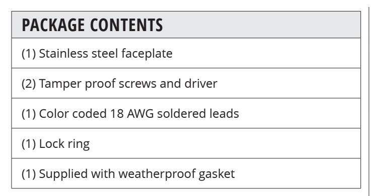
Note: Mortise Cylinder Sold Separately
1. GENERAL DESCRIPTION
Camden key switches are designed to work with most 1", 1 1/8" or 1 1/4" mortise cylinders, and with different types of cams.
One or two switches may be installed, either momentary and/or maintained (alternating on/off).
2. SPECIFICATIONS
| Input Voltage | 12-24V AC/DC |
|---|---|
| Contact Rating |
6A @ 30VDC (Standard),
15A @ 30VDC (Optional) |
| Switch Life | 100,000 cycles |
| Temp Range | 32°F - 85°F (0°C to +85°C) |
| Standard Finish | Stainless steel |
| Dimension |
4 1/2" W x 4 1/2" H x 1.5" D
(114mm x 114mm x 38mm) |
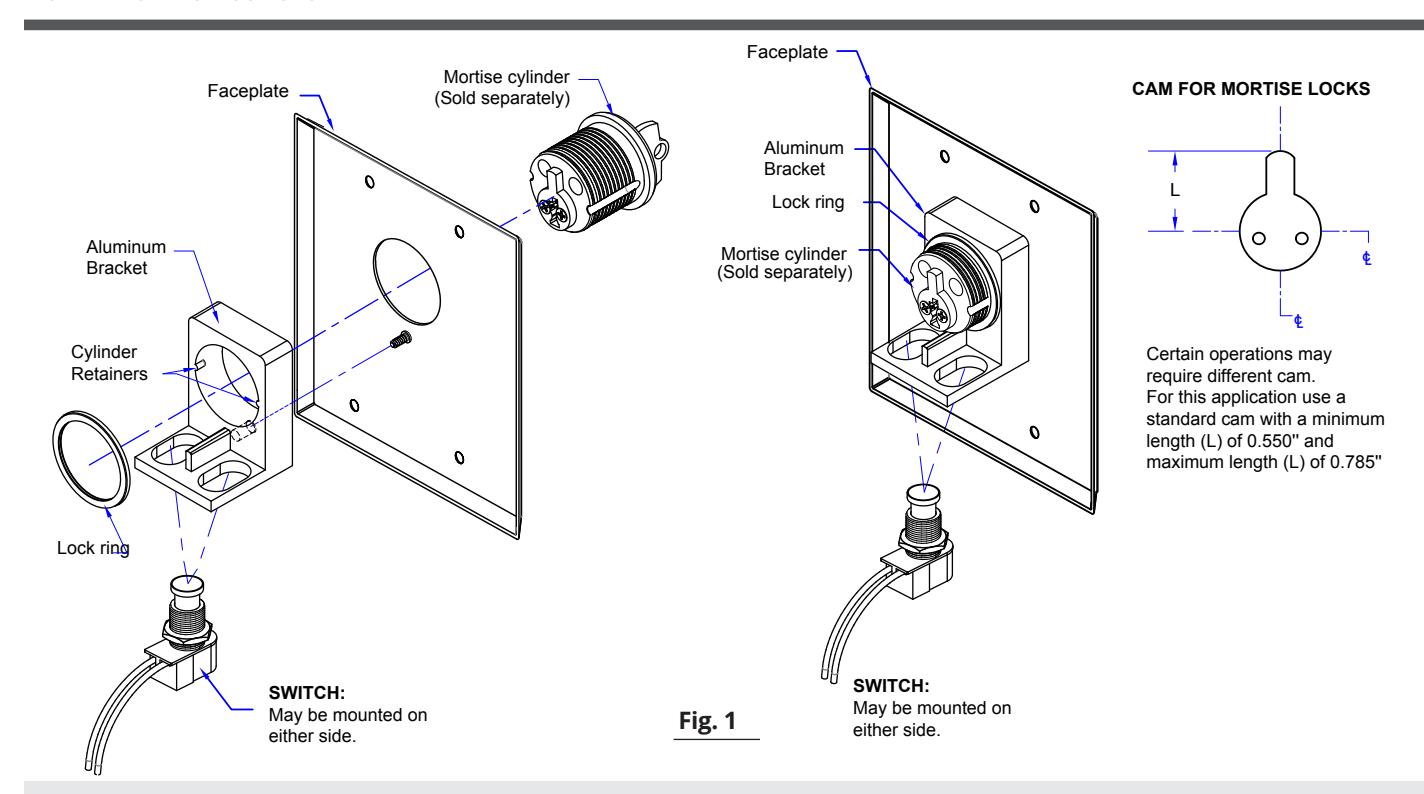
3. INSTALLATION
1. Fit the aluminum bracket against the stud on the back of the FACEPLATE. Insert the mortise cylinder through the front of the FACEPLATE being sure to align the grooves on the sides of the cylinder with the corresponding "Retainers" on the aluminum bracket. See fig 1. Some cylinders may appear not to fit. If the grooves on the side of the cylinder are irregular and do not align with the retainers on the bracket, use a metal file to file down the retainers slightly.
Note –do not file the retainers off completely as they prevent the cylinder from spinning in the FACEPLATE.
- 2. Thread the brass cylinder lock ring onto the back of the cylinder and tighten to secure the aluminum bracket in place.
- 3. The switch(es) provided may be mounted in either the left or the right hole on the aluminum bracket. Thread the octagonal nut (spacer ring) on to the bushing (stem) of the switch before placing the switch in the hole
- 4. Insert the switch up through the bottom of the desired hole. Secure the switch in place by screwing the round threaded washer onto the top of the switch.
- 5. Turn the key in the cylinder and ensure the cam lines up with the top of the switch squarely in the center. Adjust the switch in the slotted hole until the cam lines up with in the center of the switch. It does not affect operation of the cam if the cylinder rests against the switch, so long as the switch is not fully depressed until activated by a turn of the key. If the cam does not depress the switch, or blocks the switch, as needed. Extra spacers are provided and may be used as required.
- 6. Once the electrical connectors are completed (see fig 2), if necessary, attach the unit to the switch box, wall, or receptacle box using the supplied tamperproof or stainless steel Phillips screws.
4. WIRING
| WIRING LAYOUT & COLOR CODING | ||||||
|---|---|---|---|---|---|---|
|
SWITCH
TYPE |
1
SPST MOMENTARY |
2
SPST MAINTAINED |
3
SPDT MOMENTARY |
4
SPDT MAINTAINED |
5
DPDT MOMENTARY |
6
DPDT MAINTAINED |
| N.O. or N.C. | N.O. or N.C. | |||||
| COMMON | BLACK | BLACK | GREY | GREY | GREY (X2) | GREY (X2) |
|
NORMALLY
OPEN |
BLACK | BLACK | BLUE | ORANGE | BLUE (X2) | ORANGE (X2) |
|
NORMALLY
CLOSED |
BLACK | BLACK | ORANGE | ORANGE | ORANGE (X2) | ORANGE (X2) |

Momentary: When the switch is pressed the current pole will change to the opposite state until released.
Maintained: When the switch is pressed it will provide the opposite pole until the button is pressed again

Momentary: When the switch is pressed it will provide a change of state on the N.O. & N.C. poles until released
Maintained: When the switch is pressed it will provide a change of state on the N.O. & N.C. poles until button pressed again
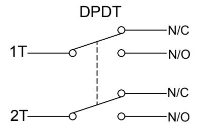
Momentary: When the switch is pressed it will provide a change of state on both of the N.O. & N.C. poles until released
Maintained: When the switch is pressed it will provide a change of state on both of the N.O. & N.C. poles until pressed again
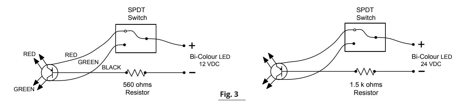
5. OPTIONAL WIRING
Key Switches may be ordered with optional LED's. These drawings show the various wiring configurations of the LED's.
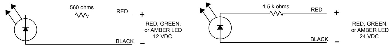
NOTE:
These LEDs are designed for DC Voltage only.
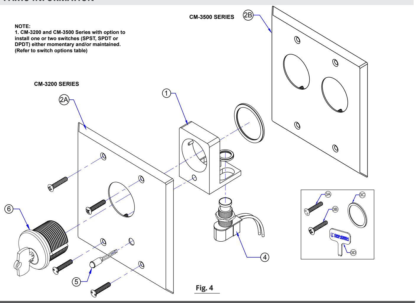
6. PARTS INFORMATION
| ORDERING INFORMATION FOR REPLACEMENT PARTS | |||||
|---|---|---|---|---|---|
|
ITEM
NUMBER |
PART NUMBER DESCRIPTION | ||||
| 1 | 60-40G011 | ALUMINUM BRACKET (TWO ALUMINUM BRACKETS FOR CM-3500 SERIES) | |||
| A. CM-3200 SERIES | CTAINLEGG CTEEL (DOUBLE CANO) FACERLATE | ||||
| 2 | 60-49B049 | STAINLESS STEEL (DOUBLE GANG) FACEPLATE | |||
| 2 | B. CM-3500 SERIES | STAINLESS STEEL (DOLIDLE CANO) FACEDLATE FOR DUAL CYLINDER VEV SWITCH | |||
| 60-49B050 | STAINLESS STEEL (DOUBLE GANG) FACEPLATE FOR DUAL CYLINDER KEY SWITCH | ||||
| PARTS KIT | ||||
|---|---|---|---|---|
|
ITEM
NUMBER |
DARTNIMBER | |||
| CM-3200 & CM-3500 SERIES | (A) 6-32 X 3/4 SNAKE EYE TAMPER PRF. SCREWS (SNAKE EYE) | |||
| 3 | 60-34B048 | (B) 6-32 X 3/4 PHILLIPS OVAL HEAD ZINC PLATED M. SCREWS (C) CYLINDER LOCK RING (D) KEY FOR TAMPER PRF. SCREWS (SNAKE EYE) | ||
| SWITCH OPTIONS | |||||||
|---|---|---|---|---|---|---|---|
| MODEL | NUMBER | ||||||
|
ITEM
NUMBER |
DOUBLE
GANG |
DOUBLE
GANG, DUAL CYLINDER |
QTY |
PART
NUMBER |
DESCRIPTION | ||
| CM-3200 | CM-3500 | 1 | 60-68D046 | SPST MOMENTARY CONTACT SWITCH, N/O 6A @125V AC, 3A@ 30V DC | |||
| CM-3205 | CM-3505 | 1 | 60-68D048 | SPST MOMENTARY CONTACT SWITCH, N/C 6A @125V AC, 3A@ 30V DC | |||
| CM-3210 | CM-3510 | 1 | 60-68D049 | SPST MAINTAINED CONTACT SWITCH, ON/OFF 6A @125V AC, 3A@ 30V DC | |||
| CM-3220 | CM-3520 | 1 | 60-68D052 | SPDT MOMENTARY CONTACT SWITCH, 6A @125V AC, 3A@ 30V DC | |||
| CM-3230 | CM-3530 | 1 | 60-68D054 | SPDT MAINTAINED CONTACT SWITCH, 6A @125V AC, 3A@ 30V DC | |||
| CM-3250 CM-3550 | 2 | 60-68D052 | SPDT MOMENTARY CONTACT SWITCH, 6A @125V AC, 3A@ 30V DC | ||||
| 4 | CM-3260 | CM-3560 | 2 | 60-68D054 | SPDT MAINTAINED CONTACT SWITCH, 6A @125V AC, 3A@ 30V DC | ||
| 3270 CM-3570 | 1 | 60-68D052 | SPDT MOMENTARY CONTACT SWITCH, 6A @125V AC, 3A@ 30V DC | ||||
| CIVI-3270 | 1 | 60-68D054 | SPDT MAINTAINED CONTACT SWITCH, 6A @125V AC, 3A@ 30V DC | ||||
| CM-3280 | CM-3580 | 1 | 60-68D053 | DPDT MOMENTARY CONTACT SWITCH, 6A @125V AC, 3A@ 30V DC | |||
| CM-3282 | CM-3582 | 2 | 60-68D053 | DPDT MOMENTARY CONTACT SWITCH, 6A @125V AC, 3A@ 30V DC | |||
| CM-3290 | CM-3590 | 1 60-68D055 | DPDT MAINTAINED CONTACT SWITCH, 6A @125V AC, 3A@ 30V DC | ||||
| CM-3292 | CM-3592 | 2 | 60-68D055 | DPDT MAINTAINED CONTACT SWITCH, 6A @125V AC, 3A@ 30V DC | |||
| SLE LED OPTI | ONS | DOUBLE LED OPTIONS | ||||||
|---|---|---|---|---|---|---|---|---|
|
ITEM
NUMBER |
MODEL
NUMBER |
QTY |
PART
NUMBER |
DESCRIPTION |
MODEL
NUMBER |
QTY |
PART
NUMBER |
DESCRIPTION |
| CM-XXXX-7012 | 1 | 60-73C008 | RED 12V LED | CM-XXXX-70122 | 2 | 60-73C008 | RED 12V LEDS | |
| CM-XXXX-7024 | 1 | 60-73C010 | RED 24V LED | CM-XXXX-70242 | 2 | 60-73C010 | RED 24V LEDS | |
| CM-XXXX-7112 | 1 | 60-73C009 | GREEN 12V LED | CM-XXXX-71122 | 2 | 60-73C009 | GREEN 12V LEDS | |
| CM-XXXX-7124 | 1 | 60-73C011 | GREEN 24V LED | CM-XXXX-71242 | 2 | 60-73C011 | GREEN 24V LEDS | |
| CM-XXXX-7212 | 1 | 60-73C009 | GREEN 12V LED | CM-XXXX-72122 | 2 | 60-73C009 | GREEN 12V LEDS | |
| 1 | 60-73C008 | RED 12V LED | 2 | 60-73C008 | RED 12V LEDS | |||
| 5 | 014 1/1/1/ 7004 | 1 | 60-73C011 | GREEN 24V LED | CM-XXXX-72242 | 2 | 60-73C011 | GREEN 24V LEDS |
| CM-XXXX-7224 | 1 | 60-73C010 | RED 24V LED | 2 | 60-73C010 | RED 24V LEDS | ||
| CM-XXXX-7412 | 1 | 60-73C014 | AMBER 12V LED | 2 | 60-73C014 | AMBER 12V LEDS | ||
| CM-XXXX-7424 | XXX-7424 1 60-73C012 AMBER 24V LED CM-XXXX-74242 | CM-XXXX-74242 | 2 | 60-73C012 | AMBER 24V LEDS | |||
| CM-XXXX-7612 | 1 | 60-66B001-12 |
BI-COLOR 12V
(3 WIRE) LED |
CM-XXXX-76122 | 2 | 60-66B001-12 |
BI-COLOR 12V
(3 WIRE) LED |
|
| CM-XXXX-7624 | 1 | 60-66B001-24 |
BI-COLOR 24V
(3 WIRE) LED |
CM-XXXX-76242 | 2 | 60-66B001-24 |
BI-COLOR 24V
(3 WIRE) LED |
|
| OPTIONAL MORTISE CYLINDERS | |||||
|---|---|---|---|---|---|
|
ITEM
NUMBER |
PART NUMBER | DESCRIPTION | |||
| CM-1000/60KD | MORTISE CYLINDER 1 1/8", KEYED DIFFERENT (SOLD SEPARATELY) | ||||
| 6 | CM-1000/60KA | MORTISE CYLINDER 1 1/8", KEYED ALIKE (SOLD SEPARATELY) | |||
| CM-307 | MORTISE CYLINDER HOUSING FOR BEST™ STYLE IC CORE (SOLD SEPARATELY) | ||||
| CM-308 | BEST™ STYLE IC CORE, KEYED DIFFERENT (SOLD SEPARATELY) | ||||
| COMPATIBLE MOUNTING BOX OPTIONS | |||||
|---|---|---|---|---|---|
|
ITEM
NUMBER |
PART NUMBER | DESCRIPTION | |||
|
CM-3200 & CM-3500
SERIES |
|||||
| 7 | CM-53 | SURFACE BOX WITH STANDARD DEPTH DOUBLE WALL, FLAME/IMPACT RESISTANT BLACK POLYMER (ABS) 4 1/2"W X 4 1/2"H X 2"D (115MM X 115MM X 51MM) | |||
| CM-67 | HEAVY DUTY 4" X 4" STAINLESS STEEL SLEEVE COVER FOR STANDARD DOUBLE GANG SURFACE BOX | ||||