CM-30EE_EELED_Manual
Open the original PDF document
View PDF


CM-30EE & CM30EE/LED Exit Switch & Integrated Timer (Ver. 2) Installation Instructions
Section 1 __________________ General Description
Camden models CM-30EE/LED are illuminated Exit switches incorporating a 30 second timer. The stainless steel faceplate is designed to mount into a 2 ½" deep single gang electrical box, included.
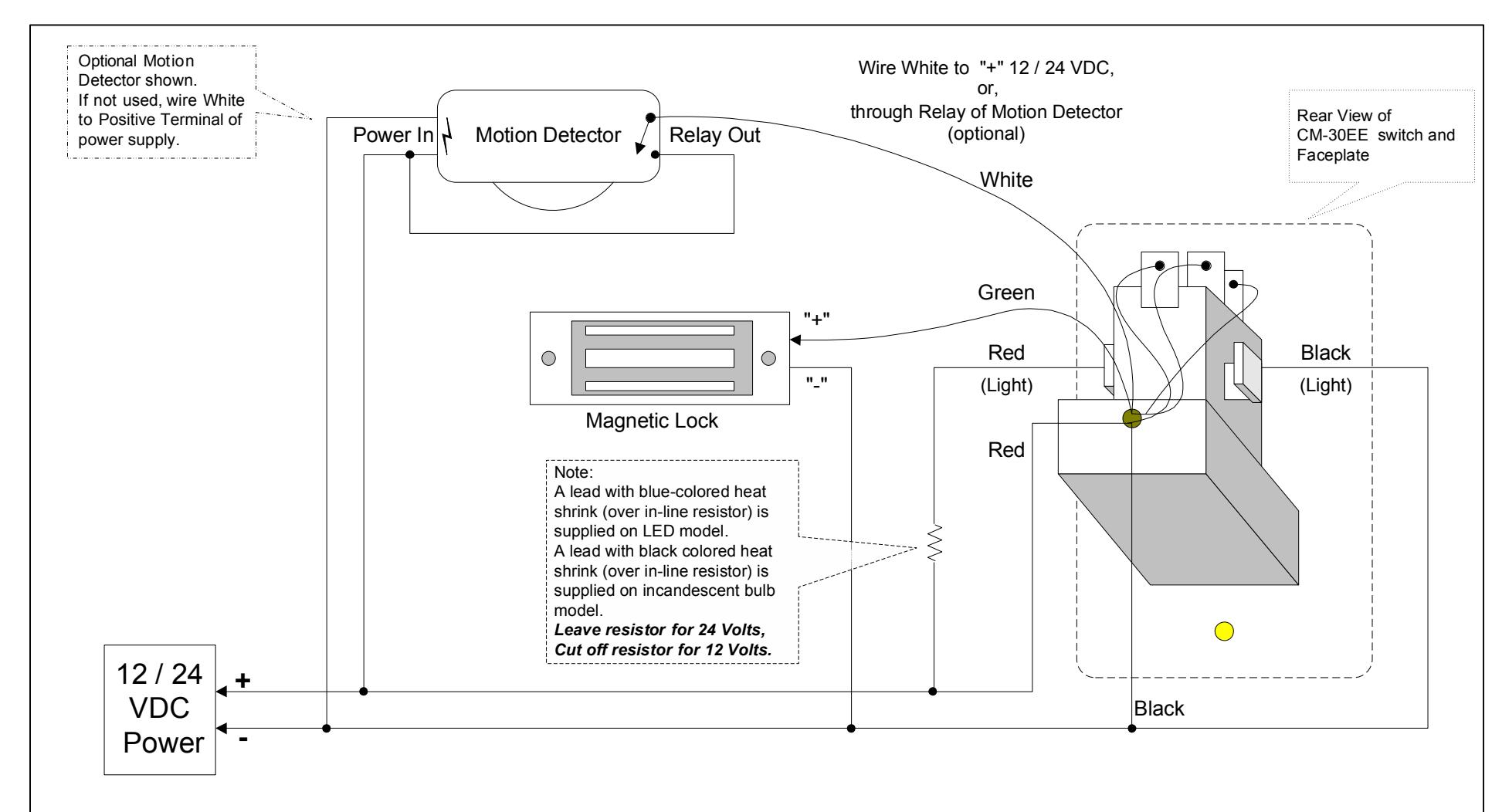
The large 2" translucent button is easy to push. CM-30EE model is supplied with a 12V AC/DC incandescent light bulb, which is accessed through the front or rear of the switch. CM-30EE/LED model is supplied with a 12V DC long-life LED. If the unit is powered 24VDC, the supplied in-line resistor must not be removed .
This switch has been designed specifically to release a magnetic lock from the inside, as per the BOCA code. When the button is pushed and released, the lock will release for 30 seconds. Re-trigger is possible at any time.
The "double break" circuitry has been designed so that even if the timer fails, depressing the switch will interrupt power to the magnetic lock.
Section 2__________________ Installation
Mounting
The unit is completely pre-wired for easy installation. Connect the appropriate wired to your devices as per the enclosed wiring diagram. Tuck wiring into box (retrofit box included), and fasten switch plate using standard or tamper screws provided.
Wiring
Six color coded leads are provided. This unit will operate on 12 or 24 VDC, with no jumper change required. For convenience it may be powered by the same power that supplies the magnetic lock. The two pairs of Red & Black wires connect to 12 or 24 VDC. One pair supplies power to the timer, and the other pair powers the light.
The internal timer and the push button are connected in series with the Green & White wires. This is how the "double break" feature works. Therefore, the unit must be wired as shown
The Green wire goes to the positive input wire of the magnetic lock, and the White wire goes to a source of + Voltage. Please refer to the enclosed wiring diagram for typical hook-up.
Important
CM-30EE models have a connected lead wire with black-colored heat shrink (over an in-line resistor). CM-30EE/LED models have a connected lead wire with blue-colored heat shrink (over an in-line resistor).
If powered 24V; Do not remove in-line resistor If powered 12V; Cut (remove) in-line resistor
Section 3 _________________ Technical Data
Lens Color Green lens Legend Push to Exit
Size 4.5"h x 2.75"w x 2.5"d
114.3mm x 69.8mm x 63.5mm Mounting 2 x #6-32 machine or tamper
screws, supplied
Operating voltage 12 / 24 Volts DC Time Delay 30 seconds Contact Rating 4 amps @ 30 VDC
Incandescent Bulb Life 15,000hrs. @ rated capacity
Section 4_________________ Limited Warranty
Camden Door Controls Inc. warrants this product to be free from defects for 3 years from date of manufacturing. Visit our web site at www.camdencontrols.com to see our complete warranty policy, including limitations and the procedures for product returns.
Questions? Call us toll-free at 1-877-226-3369
NOTES:
The light bulb (incandescent or LED), can be accessed from the front, by using a small slot (flat) screwdriver to remove the plastic lens cover or from the back. To access from the back, detach the contact block from the light fixture assembly, held in place by two plastic retaining pins. Squeeze the retaining pins and gently pull the contact block to remove the light fixture assembly.
The contact block can be reassembled into the light assembly by simply pressing it in place.
| Camden Door Controls 5502 Timberlea Blvd. Mississauga, Ontario L4W 2Z3 | |||
|---|---|---|---|
| SCALE: NONE | DRAWN BY: DGW | DATE: 02/28/03 | REVISED: 03/22/12 |
| CM-30EE Egress Switch Wiring Diagram (Ver 2.0) | |||
| DRAWING No: DRG-CM30EE-022803 FILENAME: CM-30EE | 30EE Diagram.vsd | ||