CL180-LE-Insert-Instructions
Open the original PDF document
View PDFCL 180 LOW ENERGY


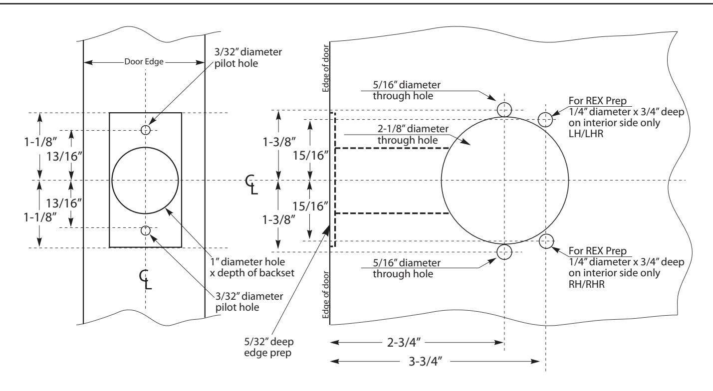
STEP 1 : The door must be machined with a 3/8" wire raceway, cylindrical lock pocket & prepped for a energy transfer hinge. Make sure the cylindrical pocket is free of debris.
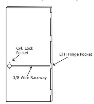
STEP 2 : Run the wires from the ETH hinge through the 3/8" raceway starting at the ETH hinge & exiting into the lock pocket.
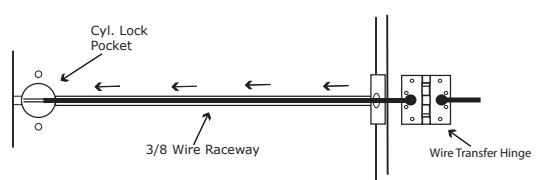
STEP 3 : Screw the ETH hinge to the door. At this time DO NOT connect the hinge wires on the jamb side to the wires coming from the power supply.
STEP 4 : Connect the wires exiting the lock pocket to the Bridge Rectifier (included).
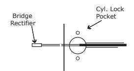
STEP 5 : Connect the Bridge Rectifier to the plug exiting the cylindrical chassis.
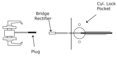
STEP 6 : Carefully slip the connected cylindrical lock chassis into the lock pocket paying close attention not to pinch any wires.
STEP 7 : Mount the cylindrical lock per manufacturer's instructions.
STEP 8 : Connect the wires from the power supply at the ETH hinge on the jamb side. Connect the hinge to the jamb.
LEGEND OF TERMS
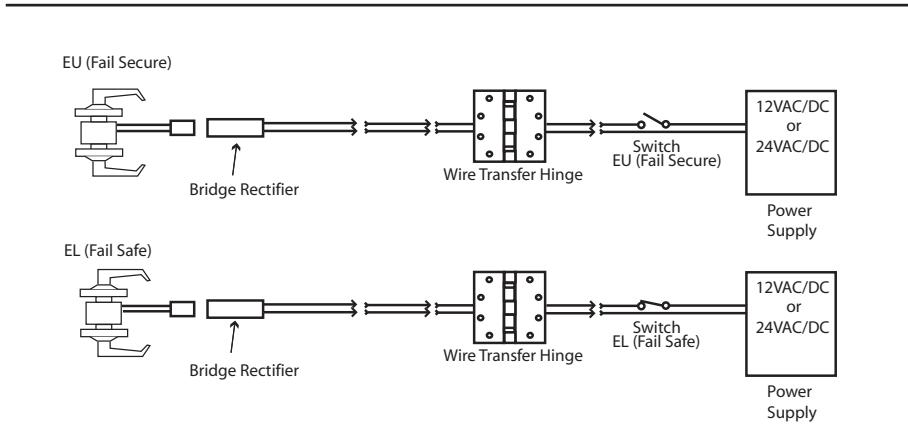
EU : (Fail Secure) When power is applied, the outside trim will unlock. When power is removed, the outside trim is locked.
EL : (Fail Safe) When power is applied, the outside trim will lock. When power is removed, the outside trim is unlocked.
REX : (Request to Exit Switch) Monitors the inside handle.
ELECTRICAL SPECIFICATIONS
SOLENOIDS:
Operating Voltage 11-30VAC/DC
VOLTSCURRENT24VAC/DC200mA12VAC/DC400mA
SWITCHES: .25A 24VAC/DC
REX:
White - Common (C) Blue - Normally Open (NO) Black - Normally Closed (NC)
SEE BACK FOR REX TEMPLATE
Template for CAT CL180 Cylindrical Lock