CI-3502 Switches Manual
Open the original PDF document
View PDF

Industrial Door and Gate Controls
CI-3502 Key Switches
INSTALLATION INSTRUCTIONS
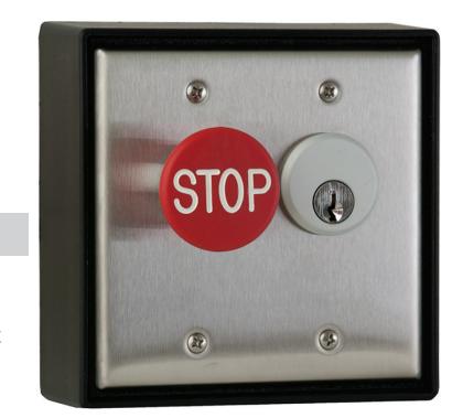
1. DESCRIPTION
Camden's mortise cylinder key switch is designed to control grilles or gates where high security key access is required. Includes double gang SS faceplate, (2) SPST N/O contacts for key switch. (1) SPST N/C contact for red
emergency stop button. Surface ABS box and weather resistant gasket. Mortise cylinder (1-1/8"), keyed different & (2) keys included.
2. SPECIFICATIONS
| Contact Type |
STOP Button:
1 x N/C SPST (Emergency STOP Pushbutton) Key Switch: 2 x N/O SPST |
|---|---|
| Contact Rating | 6A@125V AC |
| Enclosure | NEMA 1 Surface Mount |
| Endurance | 100,000 cycles |
| Mortise Cylinder | 1 1/8", keyed different, (2) keys |
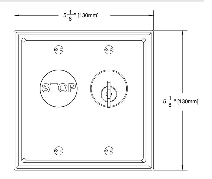
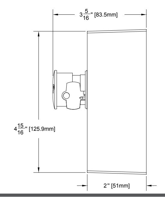
| Dimensions |
5 1/8" x 5 1/8" x 2"
(130mm x 130mm x 51mm) |
3. DIMENSIONS
4. INSTALLATION
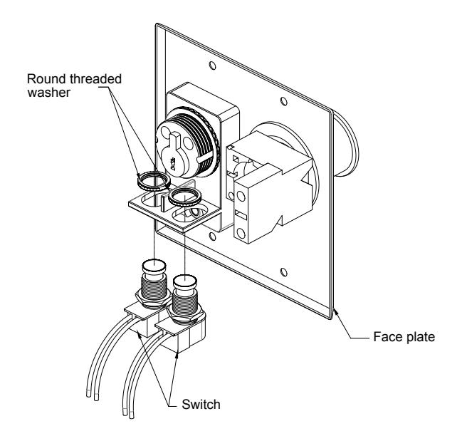
- 1. The switches provided may be mounted in the left and the right holes on the back of the faceplate. Thread the octagonal nut (spacer ring) on to the bushing (stem) of the switch before placing the switch in the hole.
- 2. Insert the switch up through the bottom of the desired hole. Secure the switch in place by screwing the round threaded washer onto the top of the switch.
- 3. Fit the mortise cylinder through the front of the face plate being sure to align the grooves on the sides of the cylinder with the corresponding "retainers" on the back of the face plate.
- 4. Push firmly on the cylinder, until it snaps into place, lying flush in the front of the face plate (aluminum models only). Note that some cylinders may appear not to fit in the face plate. If the grooves on the side of the cylinder are irregular and do not align with the retainers on the back of the faceplate, use a metal file to file down the retainers slightly.
Note: Do not file the retainers off completely as they prevent the cylinder from spinning in the face plate.
- 5. Thread the brass cylinder lock ring onto the back of the cylinder, and tighten in place.
- 6. Turn the key in the cylinder, and ensure the cam hits the top of the switch squarely in the center. Adjust the switch in the slotted hole until the cam hits in the center. It does not affect operation of the cam if the cylinder rests against the switch, so long as the switch is not fully depressed until activated by
a turn of the key. If the cam does not depress the switch, or blocks the switch from resetting, raise or lower the octagon nut located under the switch, as needed. Extra spacers are provided and may be used as required.
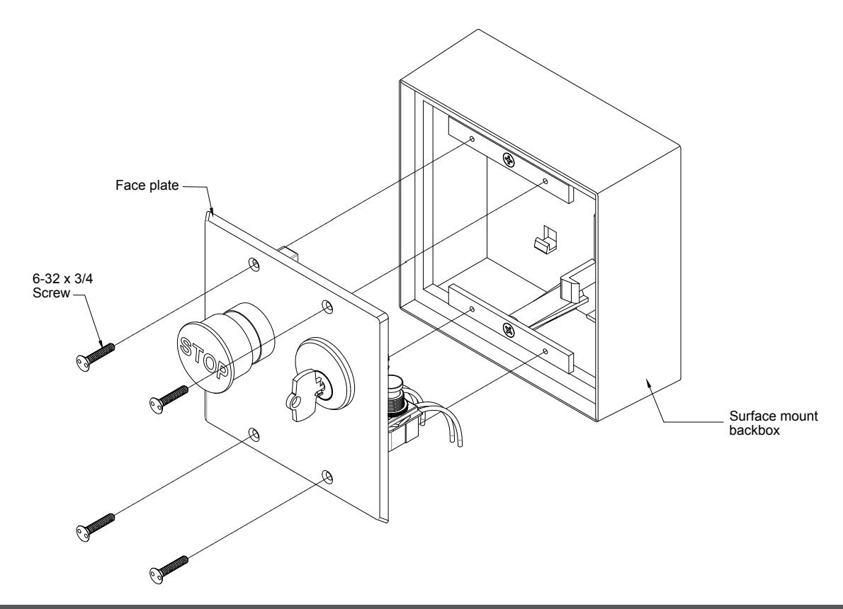
7. Once the electrical connections are completed (see below), attach the unit to the switch box, wall, or receptacle box using the supplied tamperproof or stainless steel Phillips screws. For outdoor use, place the rubber weather proofing gasket behind the face plate prior to securing to the back box or wall.
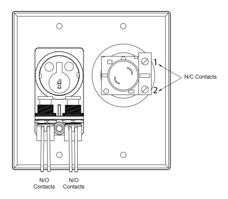
Momentary: SPST switches have normally open (N.O.) 6 amps @ 12/24/30 VAC.
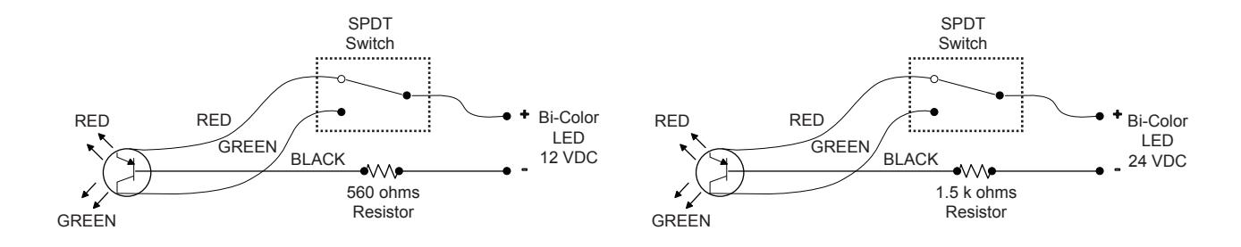
6. OPTIONAL LED WIRING
5. WIRING
Key Switches may be ordered with optional LED's. This drawings show the various wiring configurations of the LED's.
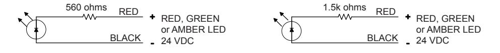
NOTE: These LED's are designed for DC Voltage only